Multi-state DC-DC converter

a dc-dc converter and multi-state technology, applied in the direction of automatic control, process and machine control, instruments, etc., can solve the problem of dc supply voltage drop of the battery, and achieve the effect of short time delay and very rapid respons

Active Publication Date: 2011-11-03
ANALOG DEVICES GLOBAL
View PDF7 Cites 19 Cited by
  • Summary
  • Abstract
  • Description
  • Claims
  • Application Information

AI Technical Summary

Benefits of technology

[0033]responding to a predetermined logic level on the control terminal of the first or second controllable switch by setting the first or second controllable switch to a closed state. The current sensing circuit automatically changes from the closed to the open state in response to a change of direction of the charging current flowing through the controllable switch. In an advantageous variant, the current sensing circuit is additionally responsive to a second predetermined logic level on the control terminal to change from the closed to the open state. In this manner the first or second controllable switch may either automatically change to its open state in response to a change of direction of the charging current it may be forced to its open state by the digital controller. However, in both embodiments, the digital controller can manipulate the control terminal or terminals to force the first and/or second controllable switches to closed states by simple level based logic signals.
[0034]In certain embodiments of the invention, the DC-DC converter circuit is configured to change between continuous and discontinuous mode operation substantially instantaneously depending on a loading of the negative or positive DC voltage node. The ability of this DC-DC converter embodiment to change from one to another one of the first, second and third converter states substantially instantaneously indep

Problems solved by technology

Furthermore, the DC supply voltage delivered by

Method used


Image

  • Multi-state DC-DC converter
  • Multi-state DC-DC converter
  • Multi-state DC-DC converter

Examples


Embodiment Construction

[0051]In the following section reference is made to the accompanying figures, which show by way of illustration a preferred embodiment of the invention.

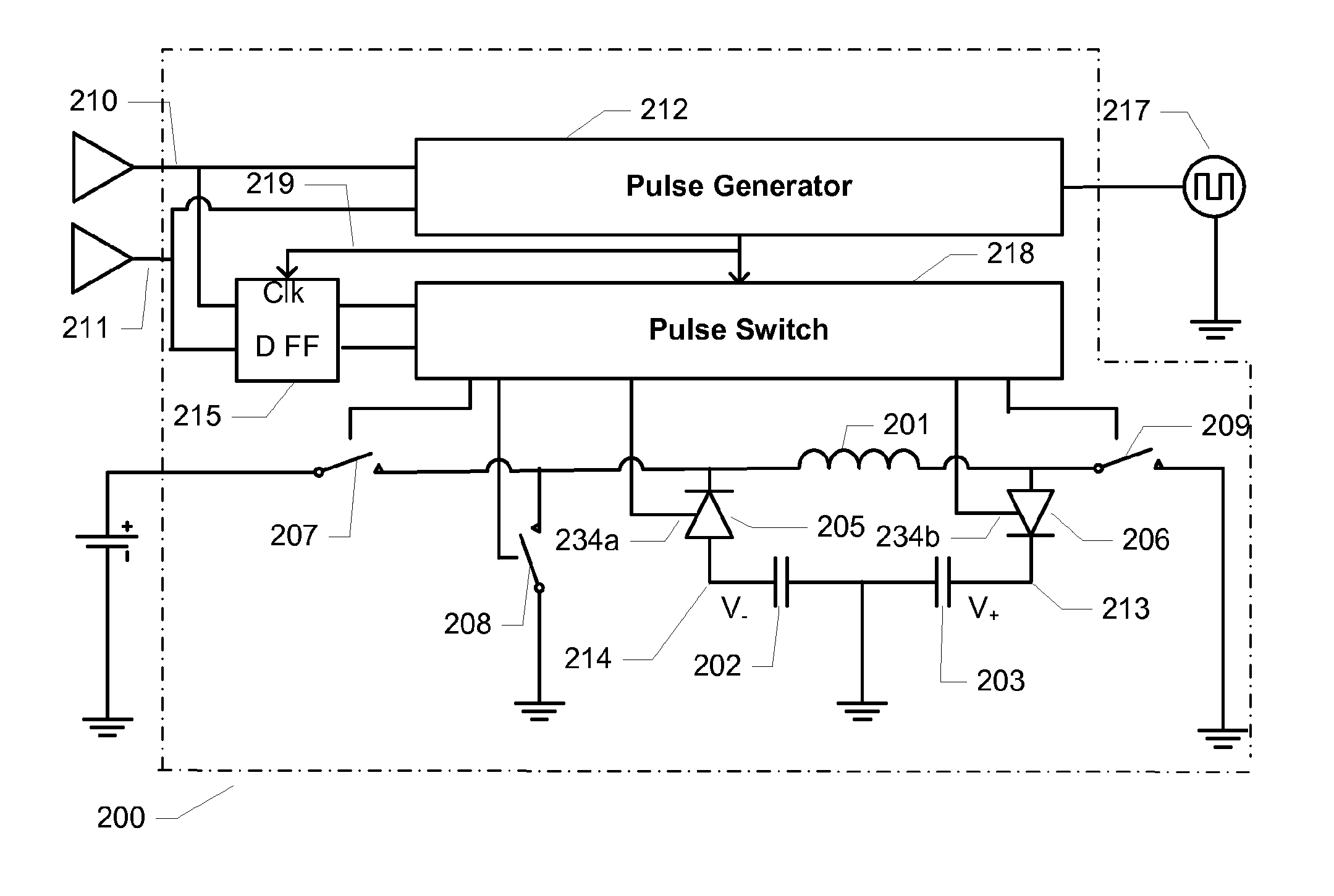
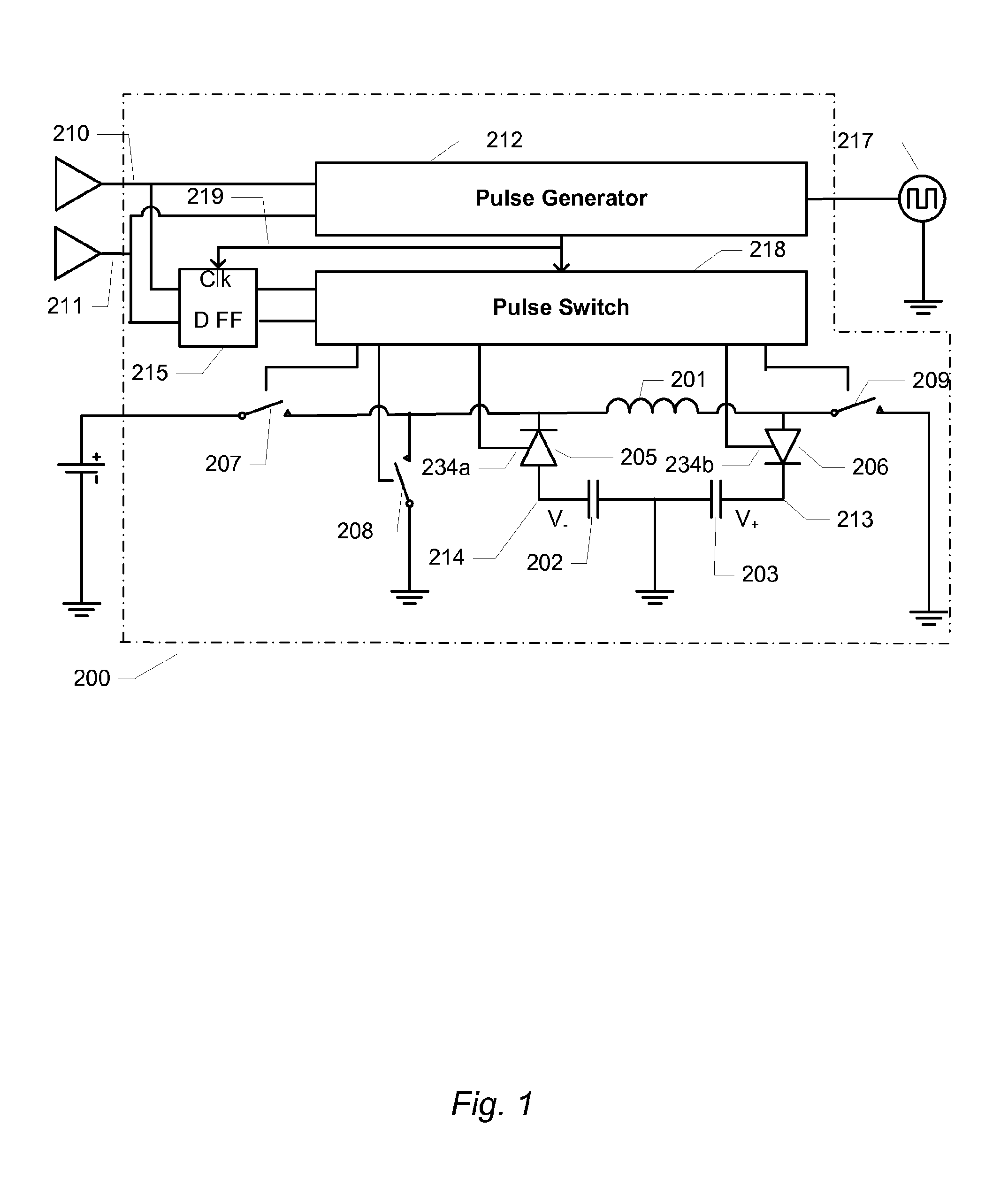
[0052]FIG. 1 depicts a simplified schematic diagram of a DC-DC converter assembly 200 comprising a DC-DC converter circuit in accordance with a preferred embodiment of the invention. The DC-DC converter circuit or DC-DC converter is coupled to a pair of external supply capacitors 202, 203 and an external inductor 201 by respective coupling terminals (not shown) to form the present DC-DC converter assembly 200. The DC-DC converter is well-suited to produce adaptive or adjustable positive and negative DC supply voltages for a class-H audio amplifier. However, it is understood that the illustrated DC-DC converter may be connected to other types of loads.

[0053]The positive and negative DC output voltages from the DC-DC converter should track output signal amplitude of the interconnected class-H audio amplifier (400 on FIG. 4) with an ess...


PUM


Abstract

DC-DC converters adapted to provide two or more DC output voltages. More particularly, a multi-state or mode DC-DC converter circuit comprising first and second controllable switches configured for unidirectional conduction of charging current.

Description

RELATED APPLICATIONS[0001]This application is a 35 U.S.C. §371 National Phase of International Application No. PCT / EP2009 / 062663 filed on Sep. 30, 2009, which claims priority to U.S. Provisional Application No. 61 / 104,823 filed on Oct. 13, 2008, the disclosures of which are herein incorporated by reference in their entireties.FIELD OF THE INVENTION[0002]The present invention generally relates to DC-DC converters adapted to provide two or more DC output voltages. More particularly, the invention relates to a multi-state or mode DC-DC converter circuit comprising first and second controllable switches configured for unidirectional conduction of charging current.BACKGROUND OF THE INVENTION[0003]DC to DC (DC-DC) converters are in wide-spread use in portable electronic devices, which are primarily supplied with power from batteries. The portable electronic devices may be mobile terminals or portable entertainment equipment such as mobile phones, MP3 players, headphones, speakers, cellula...

Claims


Application Information

Patent Timeline
IPC IPC(8): H03G3/20H02M3/156
CPCH02M3/158H02M3/157
Inventor WISMAR, ULRIK SORENSEN
Owner ANALOG DEVICES GLOBAL
Why Eureka
Try Eureka