The design of structures in hurricane zones,
tornado alleys and other high wind prone areas is a complicated and difficult issue that has undergone much study and scrutiny over the years.
Construction designs that are resistant to strong,
high velocity winds and the dramatic pressure fluctuations and differentials they cause; are not only difficult to accomplish, but exceedingly difficult to accomplish, when guided by prior art assumptions.
Assumptions concerning the design of structures have been determined by this applicant to be, by and large, inaccurate, if not totally incorrect.
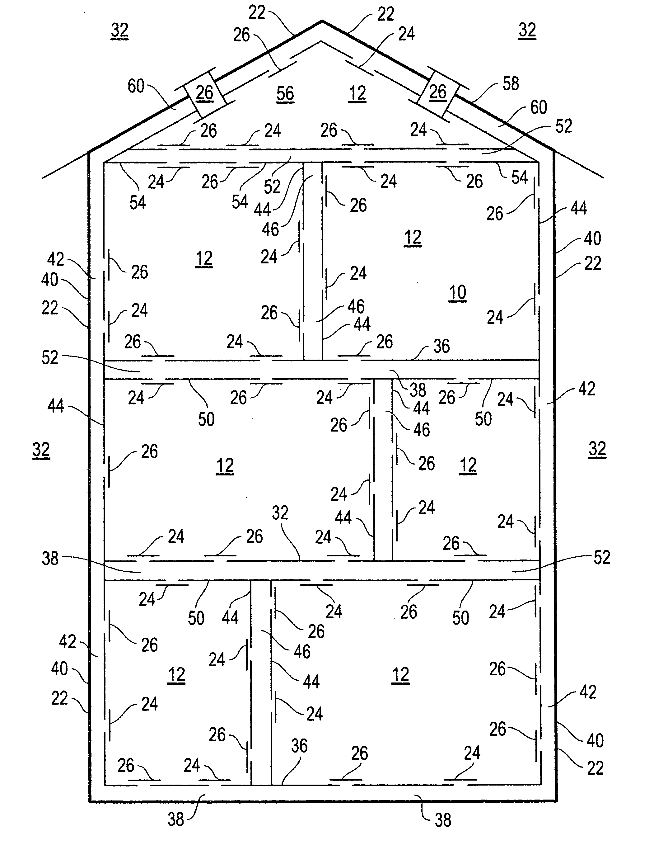
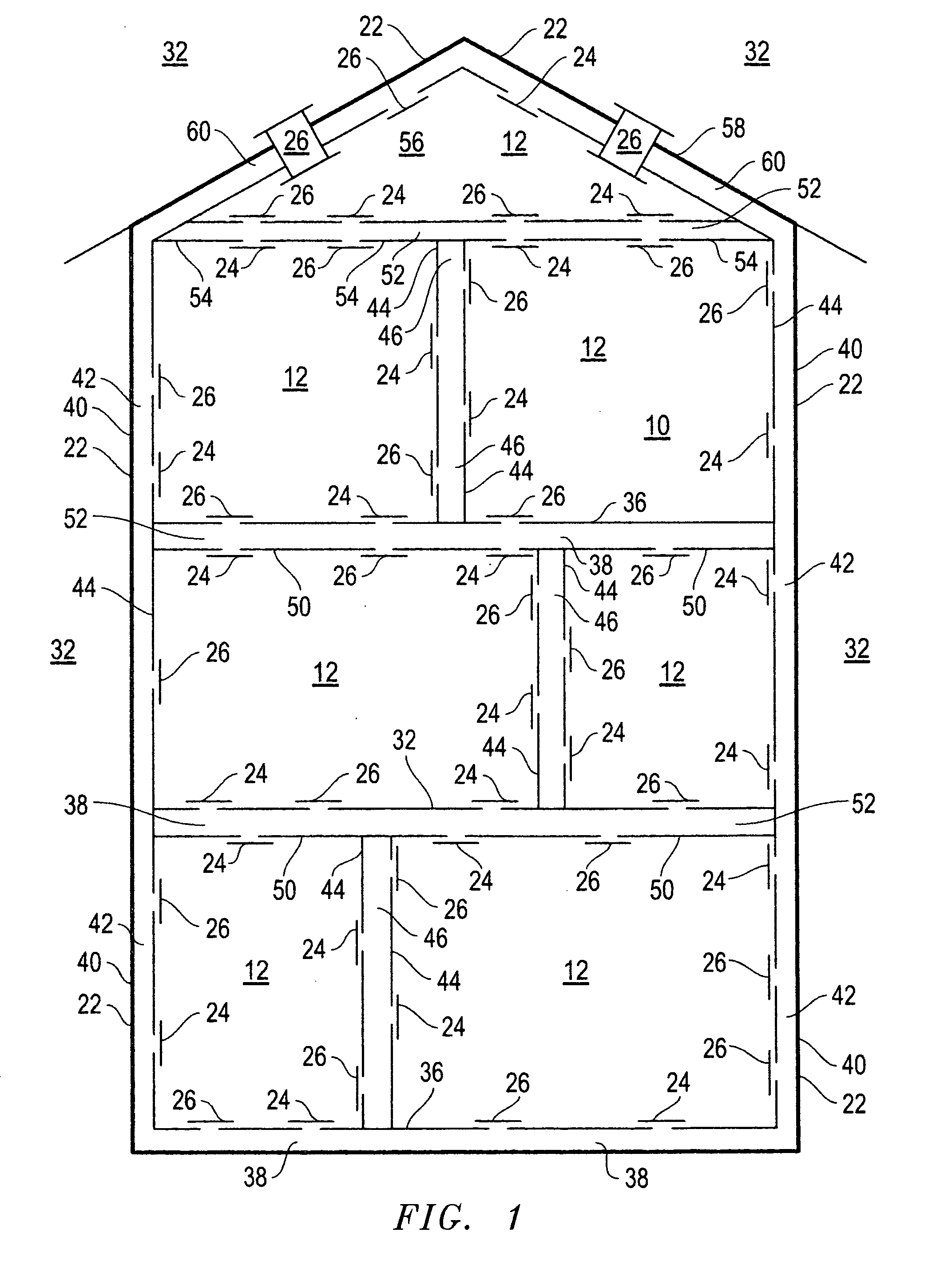
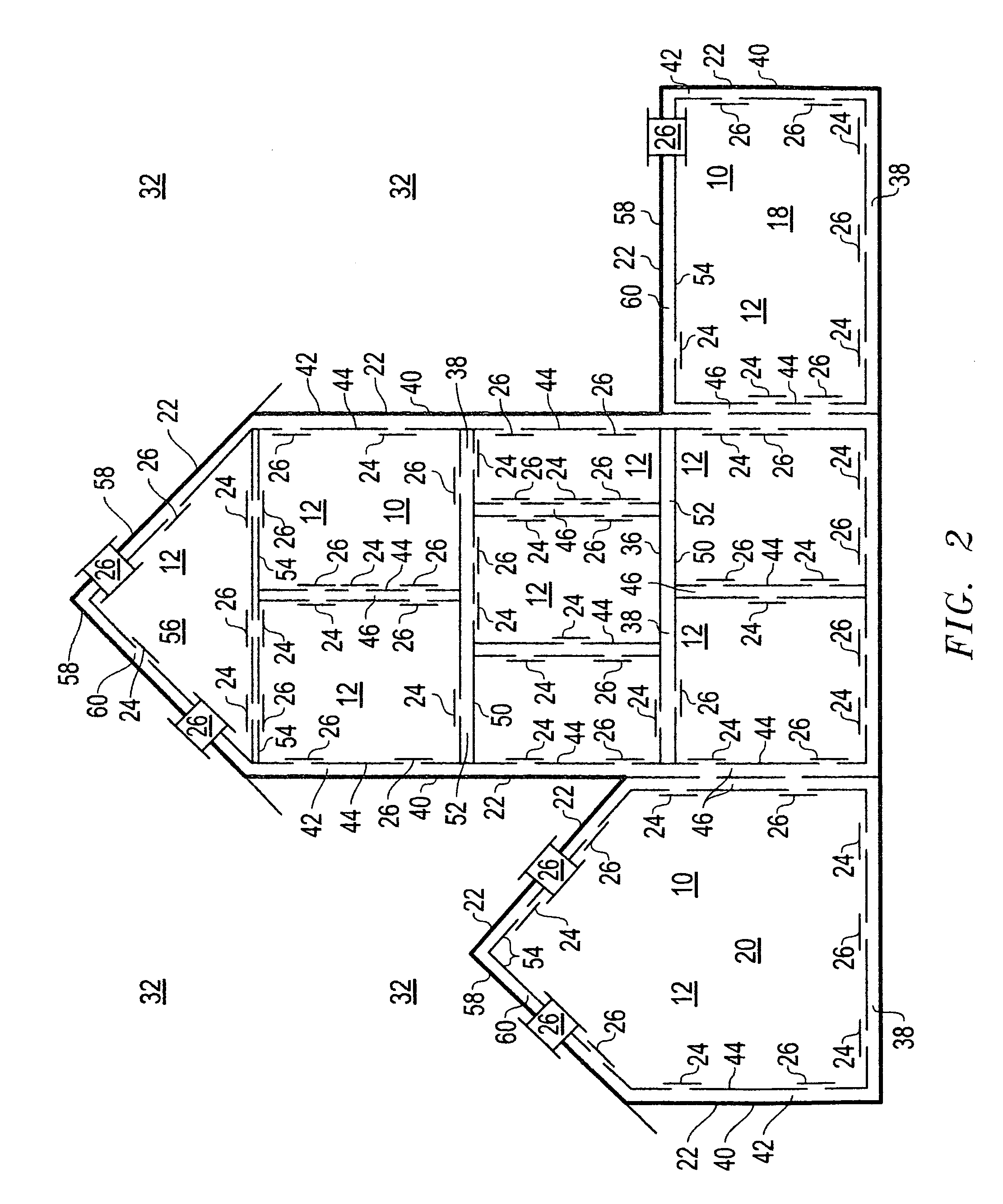
These prevalent mistakes have resulted in individual structures that incorporate multiple, yet totally separate and individual, pressure vessels, with shared vessel walls that end up working against one another and weakening all of the areas involved, which in turn weakens the entire structure.
This
common error in design has in turn lead to the
premature failure of structures during hurricanes, tornadoes and even excessive straight-line winds.
Through his extensive research
into structure pressures involved in the applicant's three granted U.S. Pat. Nos. 6,584,855; 6,968,745 and 7,127,850; the applicant has discovered that these uncontrolled, multiple, separate and individual pressure vessels existing next to each other, while sharing some vessel walls; generates a series of structure failure points during strong winds and dramatic pressure challenges.
As these
atmospheric pressure differentials pass over or even near these multiple
pressure vessel structures, the pressure differences generated between these individual and totally separate, pressure vessels within the structure, such as the enclosed, sealed, living and / or working area, the leaky
attic area, the sealed roof cavities, the sealed interstitial areas, sealed floor cavities, sealed roof cavities and sealed wall cavities, etc. . . . , that share common vessel walls, dramatically increase and can lead to the
premature failure of said structures.
It is these uncontrolled pressure differences, between these connected but totally separate and individual pressure vessels, some with shared walls, working against one another, that can literally pull, compress, tear and blow a structure apart during high wind events.
This results in an ever increasing negative pressure effect on roughly 75% of the
skin, or external surface, of a standard structure.
He quickly determined that the dramatic low pressures outside and strong winds flowing over roofs during a strong
storm are insufficient on their own to pull a single roof from a single structure, so he turned his attention to the energy these low pressures and winds generate, within the structure.
Therefore, static pressure sensors and / or pressure transducers cannot measure the pressure of moving air, so they will never accurately measure velocity / dynamic pressures, nor could they ever measure them quickly enough.
All before this applicant have attempted to determine the
differential pressure of a standard structure during a
storm, and even during normal wind conditions, using pressure transducers, static pressure sensors and / or theory, therefore they have always failed.
By then the damage to the structure will have already occurred.
This can cause these sealed external cavities to actually inflate and expand before the air can further leak into the structure core.
This expansion can weaken everything connected to these external cavities such as windows,
doors, roofs, etc. . . . It can progress to the point that windows,
doors and roofs are actually blown out of the structure.
Whether deflating or inflating, the result is the same, over time and many, many storms, or just one strong
storm, all connections in and to these external structure cavities are weakened, including roof tie downs.
Once the structure core begins to experience the ever increasing
positive pressure, it will also weaken as it inflates.
Over time the ever increasing pressure differentials between all of these totally separate pressure vessels with shared vessel walls, within the structure, begin to tear and pull against one another, further weakening the entire structure.
Applicant says they have never truly understood the real problem, so they have failed every time they tried to solve it.
This attempt at an improvement failed to produce noticeable results.
If one does not know the real problem, then they can never solve it and they are doomed to only treat the symptoms of the real problem.
The real problem is run away positive structure
internal pressure that eventually becomes so concentrated that it blows the roof off of the structure, or blows the entire structure to pieces.
In
high rise structures this run away positive structure pressure on the individual floors blows windows and walls out.
Both flat and sloped roofs failed to provide the smooth, streamlined air flow pattern required to provide a sufficient aerodynamic lifting force, especially when dormers, chimneys, roof vents, etc., were added to the calculations.
And yes, applicant is saying that “a lifting force definitely exists on the roof of a standard structure”, it is just dramatically insufficient to lift a single roof from a standard to structure, even during hurricanes and tornadoes.
The perpendicular lifting force along the sides of the structure will render wall mounted openings as used in prior art, inefficient, if not totally inoperative.
All before the applicant have failed to understand this important phenomenon, so their attempts at protecting a standard structure during high winds, have totally failed as they only treated the symptoms of the real problem, but never the real problem itself.
So, other than within the actual vortex,
high velocity, straight line winds moving parallel to the Earth's surface cause most of the structure damage encountered during tornadoes, hurricanes and all
high velocity winds.
But this is not true.
Damage to vehicles usually results from high velocity, straight line, wind getting under them and then flipping and rolling them over and over again, until they may look like they were “lifted” and dropped, but applicant's calculations do not support this theory.
Applicant also says that “people” supposedly “sucked” from vehicles are once again severely blown from the vehicle and then severely blown downstream by these same high velocity straight line winds.
Primarily because unlike the applicant, they all failed to observe the unlimited, uninterruptable, free, source of dynamic wind pressure energy that builds up within structures during high winds.
In light of this, applicant respectfully asserts that it is unfair and somewhat unjust for the USPTO to use the same patent to disallow applications concerning systems that are the opposites of each other.
Therefore, all of the controlled openings of the prior art operate only under the “external control” and “external influence” of the “externally” mounted pressure sensors, pressure transducers, controllers and / or data processors; and these devices in turn are not independent themselves because all of them are totally dependent on electrical power to operate and
electricity is the ultimate form of “external influence” and usually fails during storms.
These open-close sensors mean that even more precious seconds are lost as their information is processed by the controller and / or data processor.
Additionally, if PARKER just chose to slap shut all of his openings in this way, the structure would still be destroyed as the ever increasing buildup of
dynamic pressure within the structure eventually reaches a point where it blows the structure to bits, as described in this applicant.
They are slow to react to volumetric pressure changes, allowing structure damage to occur before the pressure sensors ever detect it and surely before the data processor and / or controller can react to the
pressure sensor information.
It is just this type of
misinformation and
system wide delays that will setup errant pressure
waves and bubbles within a structure; which will progress to the point where the protection scheme itself will eventually destroy the very structure it was installed to protect.
So if the prior art did ever add “controlled openings” to internal areas of a structure, there scheme would not have enough sensor data to determine when to open and / or when to close a single internal “opening”.
This is clear proof that none of the prior art building pressure schemes, including PARKER, ever intended to add their openings to internal areas within the structure and an issue this important cannot now be assumed or inferred.
But again none of the prior art, including PARKER, ever claims or discloses a desire to “determine the
differential pressure effects between any internal areas within the structure”; and they never could with their single
internal pressure sensor.
Their comment to the applicant was that they could not get a single building
pressure control system to react to a single opened door, much less accurately control building pressure, and “their control dampers never seemed to move”.
Applicant hereby asserts that all before him mistakenly used static pressure sensors and theory in their attempts to control building pressure, and this error in judgment never actually allowed any of them to ever actually
gain control of the pressure of a single structure since the beginning of time; so how could anyone before the applicant ever have the opportunity to see what he saw occur within a structure once he had gained control of it.
Introducing large amounts of outside air into structures in the humid Southeast is extremely difficult and improper
humidity control would spell disaster.
After many more months of applied mathematics he knew that his digital systems were operating in a
wave form frequency that resembled “
noise” on the computer data logs, producing a “failure” alarm and loss of structure
pressure control.
This in turn set up pressure turbulence
waves within the structure as his
control network strived to regain control of structure pressure; which proved impossible until the turbulent winds finally moderated.
Applicant truly doubts that any standard structure is sealed half as good as these industrial buildings were sealed, and each one of them took approximately 8-15% of the building's volume in outside air, mer minute, to keep them at only a 0.10″
positive pressure; and even with all of this they still leaked badly when impacted by 60-80 mph turbulent winds.
But neither PARKER, nor ASHRAE, nor anyone else can teach what they know nothing about.
But currently ASHRAE and just about every Mechanical Engineer in the World is doing everything they can to reduce outside air requirements and “slickly” pointing to energy savings; while our structures actually become inefficient energy hogs and mold and
mildew factories.
It is this applicant's opinion that just about every
air handler sold over the past 100 years is not really suited for its intended purpose, leaving structures operating at negative pressures; turning the “skins / external walls” of our structures into low efficient “filters”, as large amounts of dirty, hot / cold, humid air are constantly “sucked” into structures.
ASHRAE's current misguided theory of using dedicated “outside air units” causes more structure pressure problems than they solve, by duplicating air flows and generating even more structure “pressure
waves and / or bubbles”.
These Mechanical Engineers doom their projects to failure due to their lack of real world experience; by providing far too little outside air for pressurization.
The
slow speed of static pressure sensors and theory cannot account for these leaks until a whole lot of leaks have already occurred over a period of approximately 6-10 minutes, per applicant's thousands of hours spent trying to make them work.
If fact, he has never found a single structure
pressure control system based on static pressure sensors and theory, operating properly, in his life.
Static pressure sensors and theory can never determine air flow “direction”; and antiquated
thermistor technology is too slow.
They cannot teach what they know nothing about.
Applicant uncomfortably learned that even his super fast and super accurate patented dynamic building pressure control systems could not keep up with the turbulent
wind gust generated by even this weak tropical storm, even though they leave all of the antiquated prior art systems, including PARKER, in the dust.
So he knew a
tornado and / or hurricane would drive his dynamic systems into almost immediate failure, even if the power were able to stay on.
So, this on the job training taught the applicant that structures definitely leak and that the resulting high wind generated pressure fluctuations within structures, occurred faster than even his existing patented dynamic four tenths of a second systems could adapt to.
In “high wind structure protection” schemes, speed saves lives and structures, while lack thereof will end lives, allow severe injuries and destroy structures.
All of the prior art “high wind structure protection” schemes are based on “static pressure sensors and / or theory”, so they will fail and fail miserably during every
tornado they encounter.
Any scheme that employs any form of “
control theory” will waste far too much time gathering data, then “
processing” it and then deciding what to do with it; while the high winds destroys the very structure around them; even ones that employ applicant's
dynamic pressure control theory.
Therefore, all of the “controlled openings” of the prior art schemes are not fast enough, nor are they self regulating, nor are they automatic; leaving them totally externally influenced and / or totally controlled, because these openings are mounted “apart” from the pressure sensors, pressure transducers, controllers and / or data processors involved in their scheme, even when operated manually, which is just another form of external influence and / or external control.
Since neither the drawings nor specifications of the prior art, including PARKER, shows or describes any of these pressure sensors, pressure transducers, controllers and / or data processors mounted directly onto any of the individual controlled openings themselves, these controlled openings are totally incapable of regulating themselves, or any form of independent operation.
All of which would fail when the power fails.
It is just these large pressure differentials generated by the inflated high pressures that build up within these enclosed sealed internal areas within the structure, due to wind intrusion that create the potential for the explosion of these enclosed sealed, separate, internal, pressure vessels within the structure, and consequently leading to a
catastrophic failure of the entire structure.
Neither his specification nor his drawings ever mentions any requirement or desire to add openings to any internal area and / or surface, within the structure, and such an important issue cannot just now be assumed, or inferred.
Instead everyone operates under the misconception that all internal surfaces within structures must be sealed as well as possible and any holes are totally unacceptable, especially in humid climates.
To decide before all of the variables are known would lead to operational and / or
humidity problems and application
confusion.
He discovered the hard way that pressure differences within structures can dramatically affect the performance of even the best designed
humidity control system.
Also, to completely and exactly clarify such an interrelated set of variables as to which opening should be used, and under which exact humidity and
temperature and pressure conditions, would result in a
patent application that would easily be over 200 pages long and be difficult for any lay person to comprehend and be expensive and
time consuming for the applicant to file.
The resulting
confusion could easily mislead someone into using exactly the wrong opening, at exactly the wrong time, in exactly the wrong location and in exactly the wrong outside climate.
No other prior art patent in existence, offers this possibility.
One of his next door neighbors also had high quality storm shutters but several of their windows and their roof still failed.
All prior art schemes will fail, because their openings will never work fast enough, to solve what the applicant experienced.

