Total internal reflection microscope apparatus and method for analyzing fluorescent sample

a total internal reflection and microscope technology, applied in the direction of fluorescence/phosphorescence, luminescent dosimeters, optical radiation measurement, etc., can solve the problems of many technical problems, difficult realization of these methods, and inability to meet the demands only with improvements, etc., to achieve suppressed internal fluorescence of temperature controllers, high precision, and high precision

Active Publication Date: 2011-11-24
HITACHI HIGH-TECH CORP
View PDF9 Cites 4 Cited by
  • Summary
  • Abstract
  • Description
  • Claims
  • Application Information

AI Technical Summary

Benefits of technology

[0043]The present invention enables intrinsic fluorescence of the temperature controller to be suppressed, which allows highly sensitive fluorescence observation while controlling sample solution temperature with high precision. For instance, this in turn allows the throughput of single molecule DNA sequencing using a total internal reflection microscope to be improved.

Problems solved by technology

These demands cannot be met only with improvements of the conventional capillary method.
However, these methods include many technical problems.
Accordingly, it is considered that realization of these methods is difficult.
However, since these methods amplify nucleic acids to be read and sequence the amplified nucleic acids, it is difficult to further reduce the analysis cost.
However, in the method as with the above literature that performs elongation reaction and sequencing on each nucleotide, the ability that is included in the enzyme and consecutively takes in nucleotides is wasted.
However, in Non Patent Literature 5, since an objective-type total internal reflection microscope is employed, it is limited to high magnification detection of 60× or more.
However, owing to limitation of the principle employing an oil-immersion objective with a high numerical aperture, there is a drawback of limitation to observation with a high magnification of 60× or more.
Thus, there are drawbacks that operability of the sample and flexibility in arrangement of a specimen are significantly low.
However, since the thickness of the slide glass is limited to approximately 0.2 mm and thin, the number of multiplexed total internal reflections is increased.
Further, since the incident and emission positions of laser light are fixed, it is required to move the objective in order to change the position of observing a sample and thus the operation is not easy.
Accordingly, in a case of a prism type total internal reflection microscope, since a space above the objective is occupied by the prism and the space therebelow is occupied by the objective, operability of a sample and flexibility in arrangement of a specimen are low.

Method used


Image

  • Total internal reflection microscope apparatus and method for analyzing fluorescent sample
  • Total internal reflection microscope apparatus and method for analyzing fluorescent sample
  • Total internal reflection microscope apparatus and method for analyzing fluorescent sample

Examples


embodiment 1

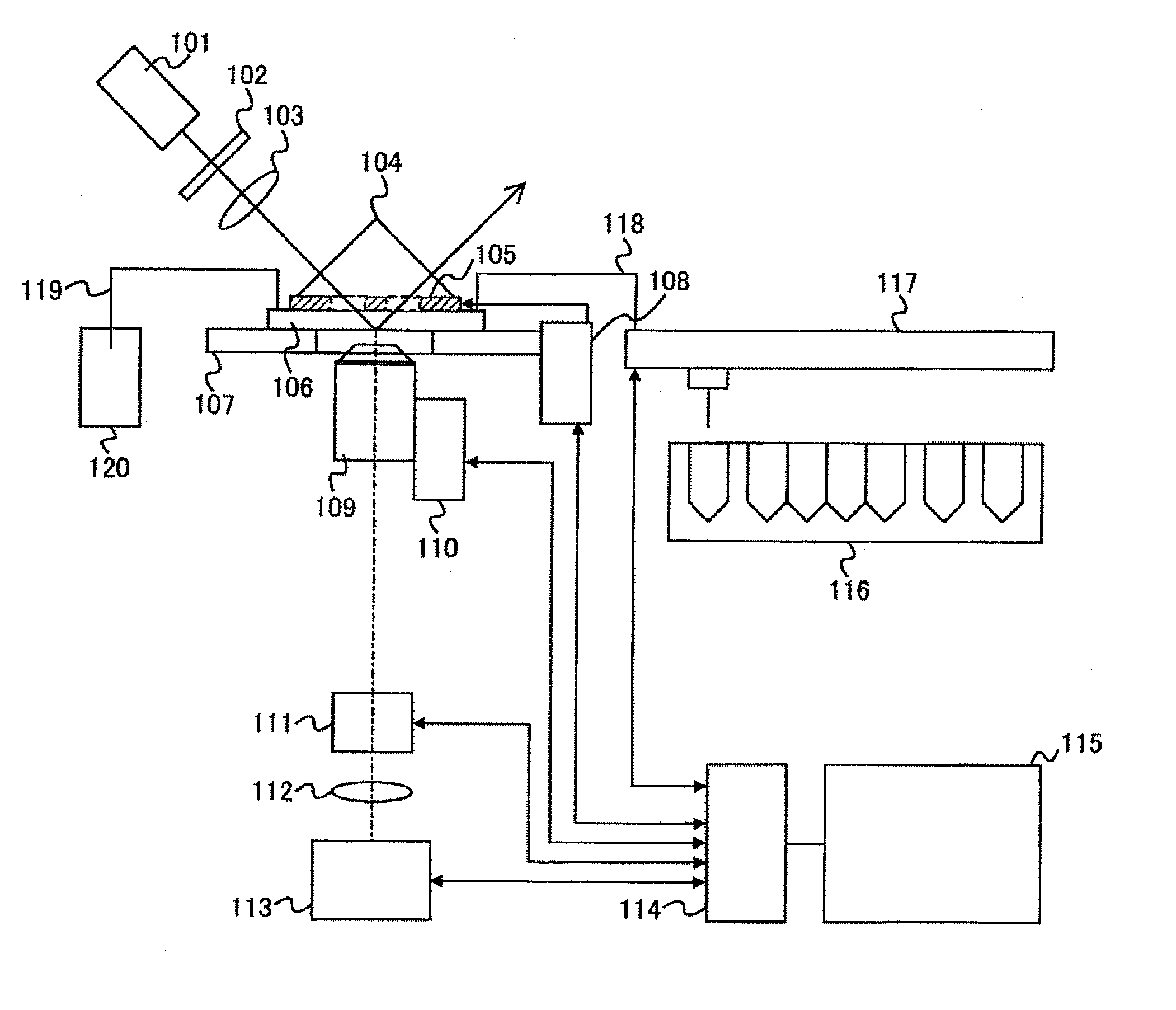
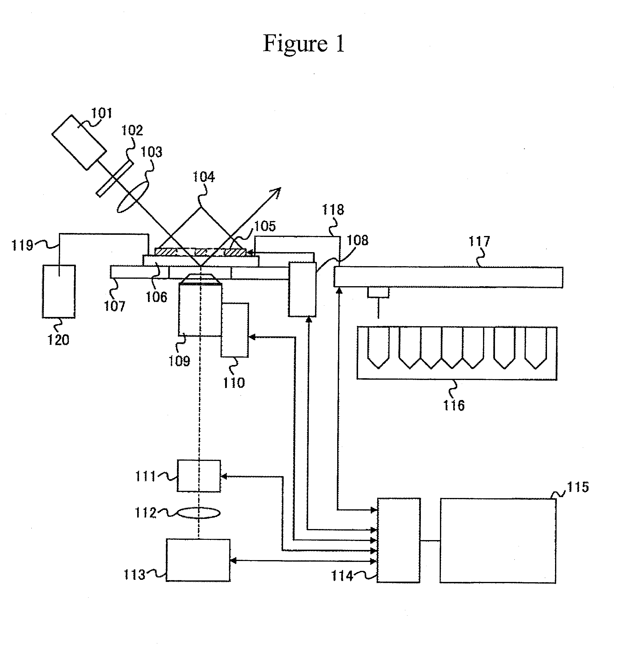
[0067]FIG. 1 schematically shows a prism type total internal reflection microscope having a local temperature control function. This microscope is a total internal reflection microscope, and controls temperature by contacting a heating or cooling device having openings at areas of incident light and reflected light with a substrate to be measured.

[0068]A laser beam oscillated by a laser 101 is circularly polarized by a λ / 4 wavelength plate 102, passes through a condenser lens 103 and subsequently is perpendicularly incident onto a prism 104. As a glass for the prism, an optical glass that can be manufactured with very high homogeneity is required. Accordingly, synthetic silica or BK7 or BSC7 with high transmittance and high homogeneity is generally adopted.

[0069]The laser beam passes through an area of an opening formed on a local temperature controller 105, which is temperature-controlled by a local temperature controller controlling unit 108, and then is incident onto a refractive...

embodiment 2

[0089]In this embodiment, two prisms are embedded in two areas of openings in the local temperature controller instead of the glycerol. Hereinafter, differences from Embodiment 1 will be principally described.

[0090]In this embodiment, as shown in FIG. 3, two prisms 301 are embedded in the respective two areas of the openings of the local temperature controller 302. The prisms 301 are intimately contact with the measurement substrate 304. It is preferable that the size of the prism be approximately from 1 mm×4 mm to 4 mm×40 mm. When the laser beam 303 is perpendicularly incident onto the prism 301, since the prism 301 is intimately contact with the measurement substrate 304, totally internally reflection occurs between the measurement substrate 304 and the solution 305 without use of the glycerol.

embodiment 3

[0091]In this embodiment, one prism is embedded in one area of an opening of a local temperature controller instead of the glycerol. Hereinafter, a difference from Embodiments 1 and 2 will be principally described.

[0092]In this embodiment, as shown in FIG. 4, a prism 401 is embedded in one area of an opening of a local temperature controller 402. It is preferable that the size of the prism be approximately from 1 mm×10 mm to 4 mm×40 mm. When the laser beam 403 is perpendicularly incident onto the prism 401, since the prism 401 is intimately contact with the measurement substrate 404, totally internally reflection occurs between the measurement substrate 404 and the solution 405 without use of glycerol.


PUM

PropertyMeasurementUnit
sizesaaaaaaaaaa
sizesaaaaaaaaaa
wavelengthsaaaaaaaaaa

Abstract

An object of the present invention relates to observation of single molecule fluorescence while temperature of a sample solution is controlled by a temperature controller and intrinsic fluorescence of the temperature controller is avoided, in a total internal reflection microscope. The present invention relates to provision of an opening at areas of the temperature controller through which incident light and reflected light pass, and configuration adopting a material with intrinsic fluorescence lower than that of the other parts, in a total internal reflection microscope including a prism and the temperature controller. The present invention enables intrinsic fluorescence of the temperature controller to be suppressed, which allows highly sensitive fluorescence observation while controlling sample solution temperature with high precision. For instance, this in turn allows the throughput of single molecule DNA sequencing using a total internal reflection microscope to be improved.

Description

TECHNICAL FIELD[0001]The present invention relates to temperature control of a total internal reflection microscope.BACKGROUND ART[0002]Total internal reflection microscopy is an observation method that allows nanoscale local excitation and has a high S / N ratio. The prime characteristics of this method are utilization of evanescent waves caused by total internal reflection of light at a boundary between two materials different in refractive index. When light is incident onto a boundary between a material 1 of refractive index n1 and a material 2 of refractive index n2 from the material 2 of the higher refractive index at a critical angle or more, the light is totally internally reflected at the boundary; this generates evanescent waves, which exponentially decays in the material 1 of the lower refractive index. The evanescent wave is light slightly leaking into a region of an extent of several tens to hundreds of nanometers from the total internal reflection boundary. Accordingly, t...

Claims


Application Information

Patent Timeline
Patent Type & Authority Applications(United States)
IPC IPC(8): G01N21/64G01N21/01
CPCG01N21/6458G02B21/16G01N2021/6432G01N21/648
Inventor MATSUI, TAKUYATAKAHASHI, SATOSHIHAGA, TAKANOBU
Owner HITACHI HIGH-TECH CORP
Why Eureka
Try Eureka