
Multiple Wavelength Optical Systems

a multi-wavelength, optical system technology, applied in semiconductor lasers, laser details, instruments, etc., can solve the problems of high high output power of native green lasers, and high level of speckle in projected images

Inactive Publication Date: 2011-11-24
CORNING INC
View PDF4 Cites 19 Cited by
  • Summary
  • Abstract
  • Description
  • Claims
  • Application Information

AI Technical Summary

Benefits of technology

[0008]In another embodiment, an optical system includes an optical source and a wavelength conversion device. The optical source may include at least one laser configured to emit a pump beam having at least two fundamental spectral peaks separated by at least 0.5 nanometers in wavelength. The wavelength conversion device comprises a non-linear optical medium characterized by a phase modulation function that provides at least

Problems solved by technology

While blue and red semiconductor lasers are currently readily available, the progress in nitride semiconductor technology has not yet resulted in a creation of native green lasers with sufficient output power, efficiency and cost effectiveness.
This allows for a small package size and reasonable efficiency, but results in a high level of speckle in projected images due to the high spectral and spatial coherence of the laser source.
At an observation point, for example in the eyes of an observer or at the sensor of a camera, these beams interfere constructively to form a bright spot, or destructively to form a dark spot, producing a random granular intensity pattern known as speckle.
Speckle causes high spatial frequency noise in the projected image.
If an image is formed on the screen using a coherent light source such as a laser beam, such granular structure will represent noise resulting in serious degradation of the image quality.
This noise presents a significant problem, particularly when the projector is used to display high spatial-frequency image content, such as text.

Method used


Image

  • Multiple Wavelength Optical Systems
  • Multiple Wavelength Optical Systems
  • Multiple Wavelength Optical Systems

Examples


Embodiment Construction

[0025]Embodiments described herein generally relate to optical systems that may reduce the appearance of speckle in images when incorporated into a laser projector system. Although embodiments described herein may be described in the context of laser projection systems, embodiments are not limited thereto. Embodiments described herein may be incorporated into systems other then laser projector systems.

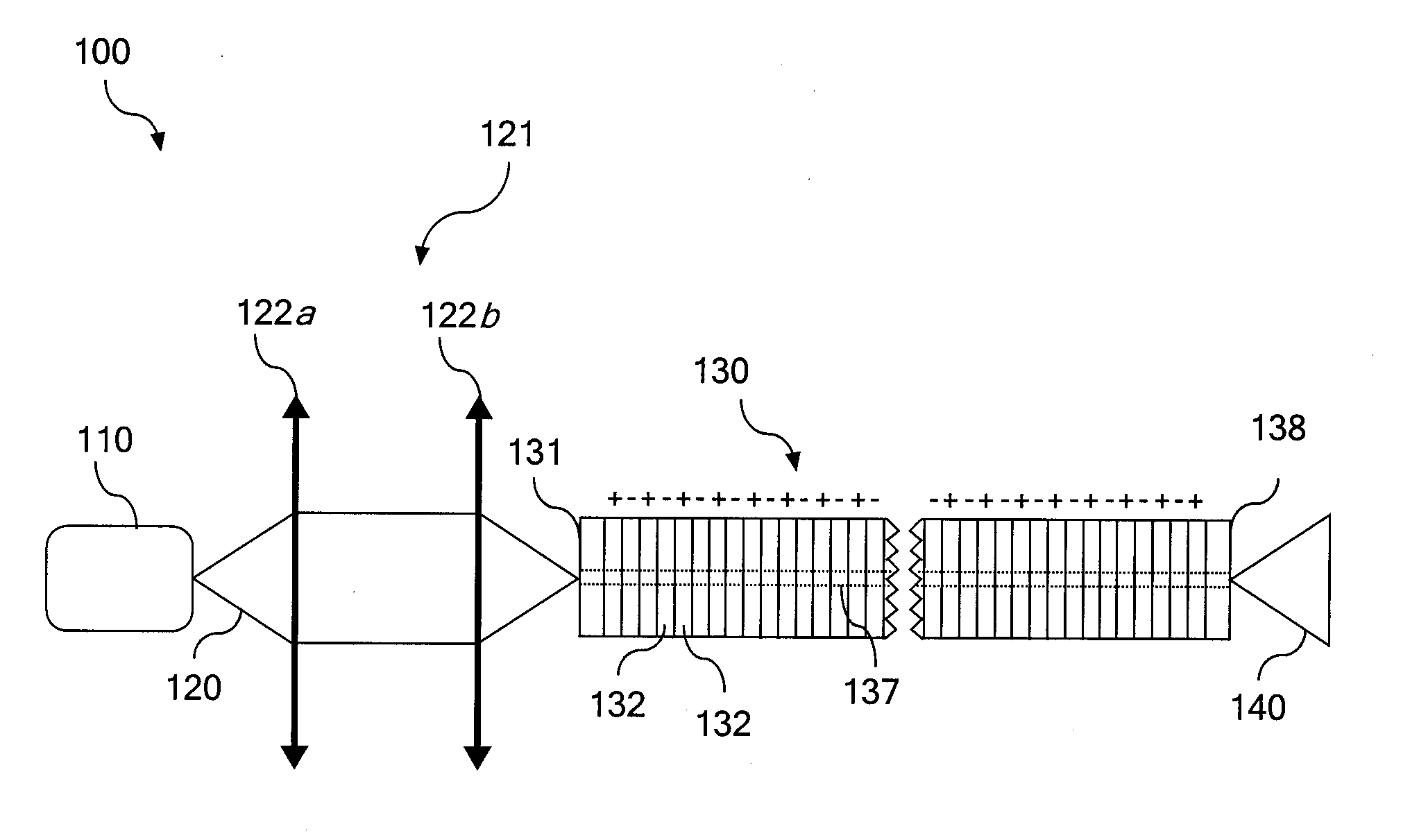
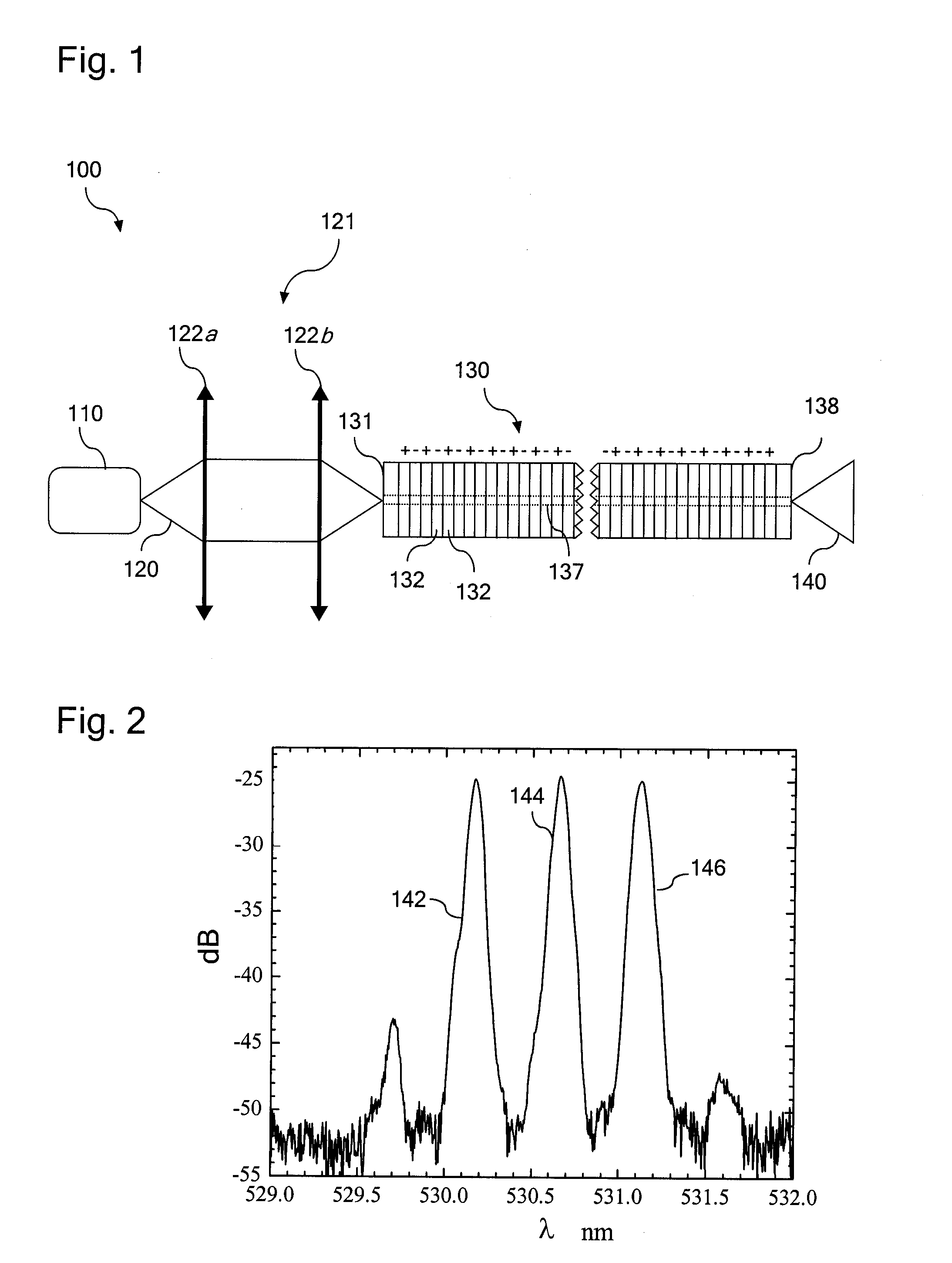
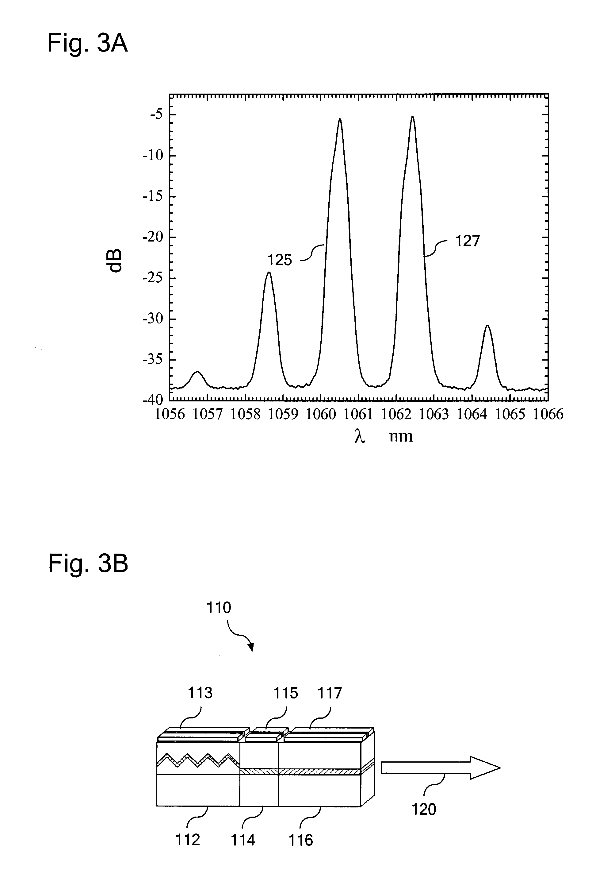
[0026]Reference will now be made in detail to embodiments of the present disclosure, examples of which are illustrated in the accompanying drawings. Whenever possible, the same reference numerals will be used throughout the drawings to refer to the same or like parts. One embodiment of an optical system is shown in FIG. 1. The optical system generally comprises at least one semiconductor laser, optional coupling optics, and a wavelength conversion device. A package controller may be included to operate the semiconductor laser and / or coupling optics. The output of the semiconductor lase...


PUM


Abstract

Optical systems operable to emit multiple frequency-converted spectral peaks are provided. In one embodiment, an optical system includes an optical source and a wavelength conversion device. The optical source may include a laser configured to emit a pump beam having at least two fundamental spectral peaks. The wavelength conversion device may include a non-linear optical medium configured to phase match the second harmonic generation of each of the at least two fundamental spectral peaks and sum-frequency generation of the at least two fundamental spectral peaks such that an output beam comprising at least three frequency-converted spectral peaks having approximately equal power is emitted from an output facet of the wavelength conversion device when the pump beam of the optical source is incident on an input facet of the wavelength conversion device.

Description

BACKGROUND[0001]1. Field[0002]Embodiments of the present disclosure generally relate to optical systems such as laser systems. More specifically, the embodiments relate to optical systems capable of producing one or more output beams having multiple frequency-converted spectral peaks for reducing the appearance of speckle in a laser-projected image.[0003]2. Technical Background[0004]While blue and red semiconductor lasers are currently readily available, the progress in nitride semiconductor technology has not yet resulted in a creation of native green lasers with sufficient output power, efficiency and cost effectiveness. An attractive alternative is to use a near-infrared (1060 nm) laser diode and generate green light by frequency doubling in a nonlinear optical medium, such as periodically poled lithium niobate (PPLN) crystal. This allows for a small package size and reasonable efficiency, but results in a high level of speckle in projected images due to the high spectral and spa...

Claims


Application Information

Patent Timeline
IPC IPC(8): H01S3/10
CPCG02F1/3532G02F1/3558G02F1/3775H01S5/1096H01S5/0092H01S5/0615H01S5/06256G02F2001/3548G02F1/3548G02F1/35G02F1/377H01S3/109
Inventor KUKSENKOV, DMITRI VLADISLAVOVICHLI, SHENPINGROUSSEV, ROSTISLAV VATCHEV
Owner CORNING INC
Learn More