Sensing and control for plasma-assisted waste gasification

a technology of plasma-assisted waste gasification and sensor, which is applied in the direction of combustible gas production, combustible gas purification/modification, and combustible gas types, etc., can solve the problems of municipal waste globally a growing problem, the sensors placed inside the gasifier to monitor the temperature are exposed to very harsh environments

Inactive Publication Date: 2011-12-01
GENERAL ELECTRIC CO
View PDF2 Cites 12 Cited by
  • Summary
  • Abstract
  • Description
  • Claims
  • Application Information

AI Technical Summary

Benefits of technology

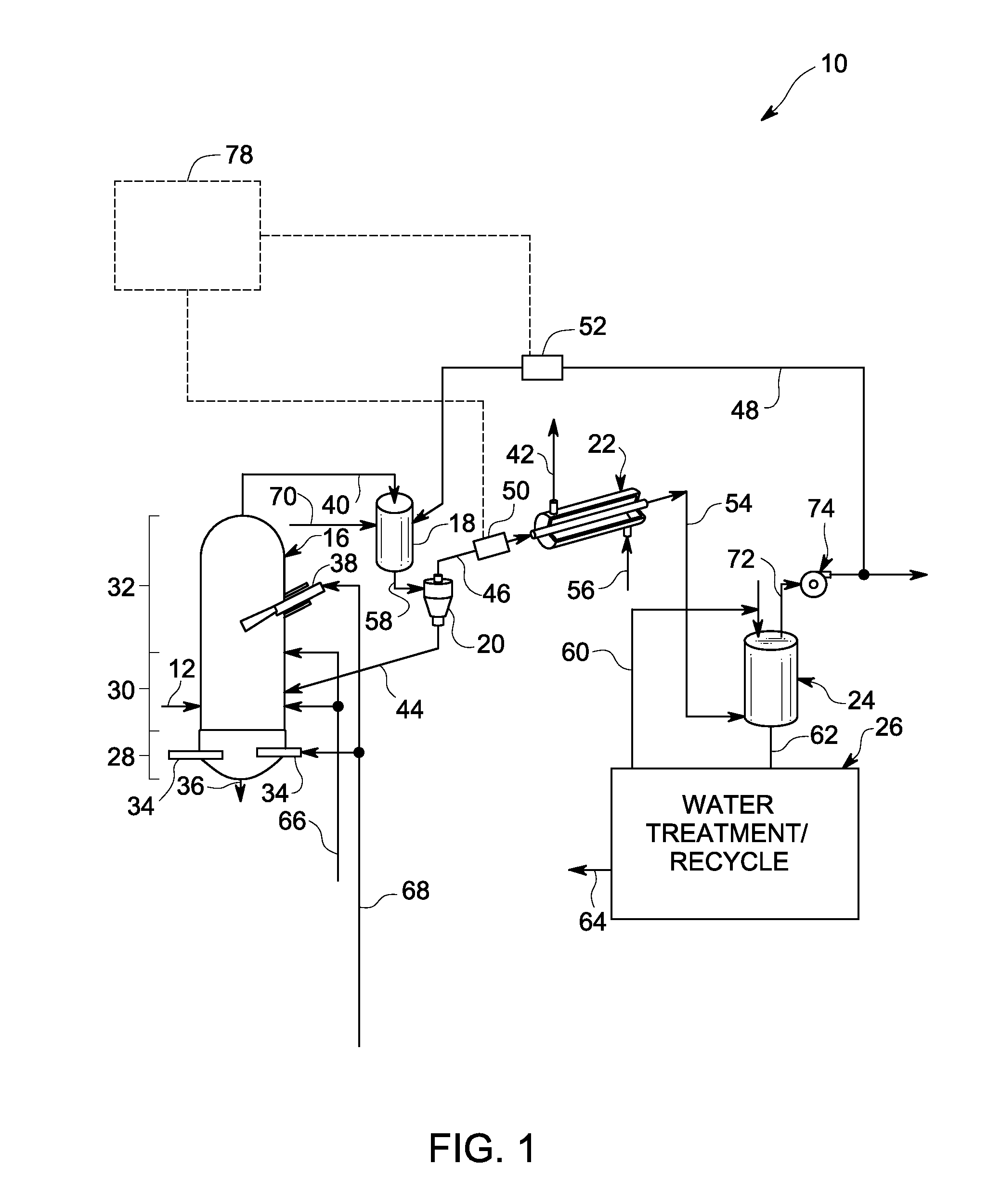
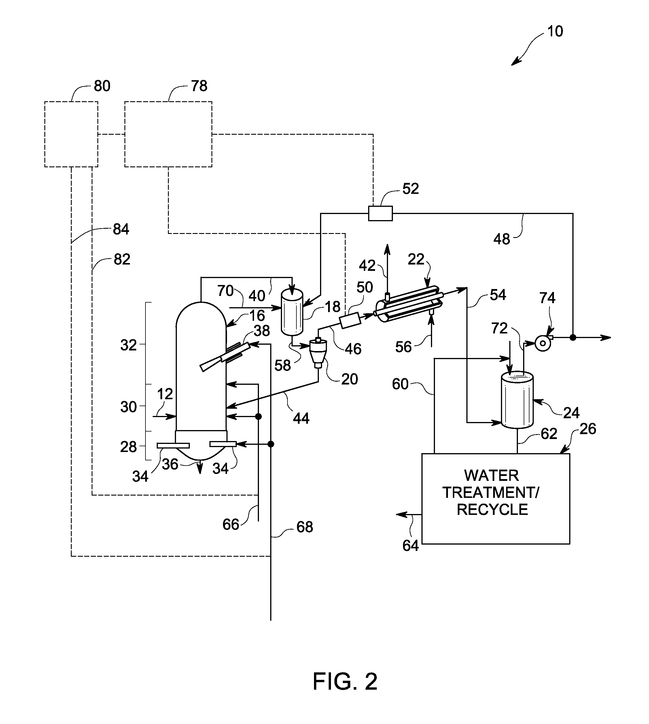
[0009]One aspect of the present invention provides a plasma-assisted waste gasification system for converting a waste stream into a synthesis gas. The gasification system includes the following components: a reactor; a gas quench unit for partially cooling the synthesis gas from the reactor, a heat recovery unit located downstream of the gas quench unit to extract thermal energy; a scrubber located downstream of the heat recovery unit; and a first sensor located between the gas quench unit and the heat recovery unit. The first sensor is used to measure a first temperature and first flow rate of the synthesis...

Problems solved by technology

Municipal waste is globally a growing problem.
In addition, the tipping fees for landfills are increasing due to land constraints or governmentally mandated closures, which are in place in multiple countries, particularly in Asia and in the European Union, or will be in the near future.
Any sensors placed inside the gasifier to monitor the temperature are exposed to very harsh environments, for example, very high temperatures and corrosive components.
Hence, it is very difficult to directly measure the temperature of the gasifier, which is critical to ensure proper decomposition of all organics into syngas.
It is becoming less desirab...

Method used


Image

  • Sensing and control for plasma-assisted waste gasification
  • Sensing and control for plasma-assisted waste gasification
  • Sensing and control for plasma-assisted waste gasification

Examples


Embodiment Construction

[0015]While only certain features of the invention have been illustrated and described herein, many modifications and changes will occur to those skilled in the art. It is, therefore, to be understood that the appended claims are intended to cover all such modifications and changes as fall within the true spirit of the invention. In the specification and claims, reference will be made to a number of terms, which have the following meanings.

[0016]The singular forms “a”, “an” and “the” include plural referents unless the context clearly dictates otherwise. Approximating language, as used herein throughout the specification and claims, may be applied to modify any quantitative representation that could permissibly vary without resulting in a change in the basic function to which it is related. Accordingly, a value modified by a term such as “about” is not to be limited to the precise value specified. In some instances, the approximating language may correspond to the precision of an in...


PUM


Abstract

A plasma-assisted waste gasification system including a sensing mechanism and process for converting waste stream reaction residues into a clean synthesis gas (syngas) is disclosed. The gasification system includes a first sensor located between a gas quench unit and a heat recovery unit to measure a first temperature and first flow rate of the synthesis gas exiting the gas quench unit; a second sensor to measure a second temperature and a second flow rate of a low temperature synthesis gas entering the gas quench unit; wherein the first sensor and the second sensor are connected to an inferential sensing mechanism. The inferential sensing mechanism is capable of estimating the temperature of the synthesis gas in the reactor, based on the measured first temperature and first flow rate, and the measured second temperature and second flow rate, using a mass-energy balance relationship that is based on the measurements of the two sensors. Another aspect of the invention relates to a control unit to control the temperature of the reactor to a required operating temperature range.

Description

[0001]This application claims the benefit of U.S. application Ser. No. 12 / 209011, filed Sep. 11, 2008, which claims the benefit of U.S. Provisional Application Ser. No. 60 / 971609, filed Sep. 12, 2007.BACKGROUND[0002]Municipal waste is globally a growing problem. Landfills generate methane that is a green house gas concern. In addition, the tipping fees for landfills are increasing due to land constraints or governmentally mandated closures, which are in place in multiple countries, particularly in Asia and in the European Union, or will be in the near future. Incineration can be used, but this is sometimes not a good option for the future, due to environmental concerns.[0003]Gasification is a process that converts carbonaceous materials, such as coal, petroleum, or biomass, into gases, such as carbon monoxide and hydrogen, by reacting the raw material at high temperatures with a controlled amount of oxygen. The resulting gas mixture is called synthesis gas or “syngas” and is in itse...

Claims


Application Information

Patent Timeline
IPC IPC(8): B01J19/08H05F3/06
CPCC10J2200/12Y02E20/16C10J3/723C10J3/84C10K1/026C10K1/101C10J2300/0946C10J2300/1238C10J2300/1634C10J2300/169C10J2300/1884F23G2201/301F23G2201/40F23G2204/201C10J2200/152C10J3/18B09B3/00C10J3/00
Inventor KUMAR, ADITYANIELSEN, MATTHEW CHRISTIANSHI, RUIJIE
Owner GENERAL ELECTRIC CO
Why Eureka
Try Eureka