Ion beam sputter target and method of manufacture

a technology of sputtering target and sputtering method, which is applied in the field of sputtering target and method of manufacture, can solve the problems of high cost and time-consuming empirical procedure, insufficient use, and weak composition-dependent sputtering yield ratio in alloys or components, and achieve the effect of effective pvd coating or other sputtering process

a technology of sputtering target and sputtering method, which is applied in the field of sputtering target and method of manufacture, can solve the problems of high cost and time-consuming empirical procedure, insufficient use, and weak composition-dependent sputtering yield ratio in alloys or components, and achieve the effect of effective pvd coating or other sputtering process

US20110297535A1Active Publication Date: 2011-12-08UT BATTELLE LLC +2

Image

  • Ion beam sputter target and method of manufacture
  • Ion beam sputter target and method of manufacture
  • Ion beam sputter target and method of manufacture

Examples


Embodiment Construction

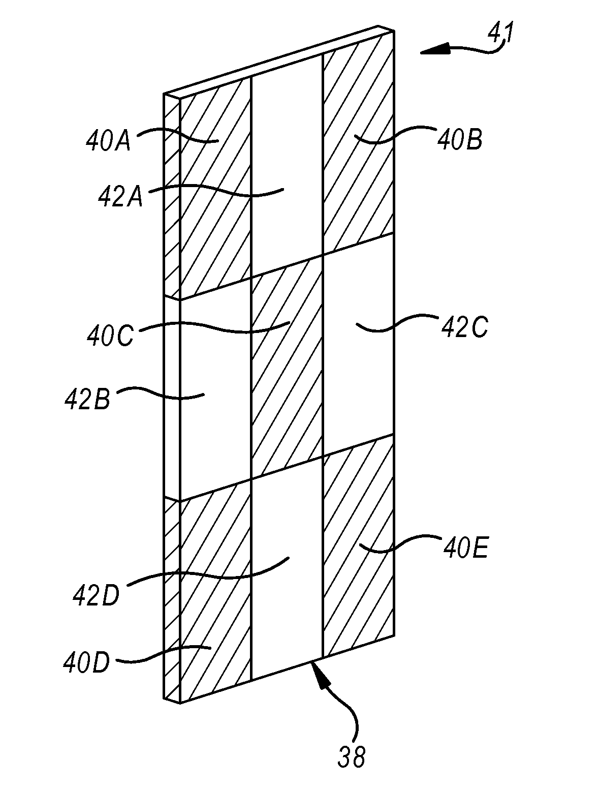
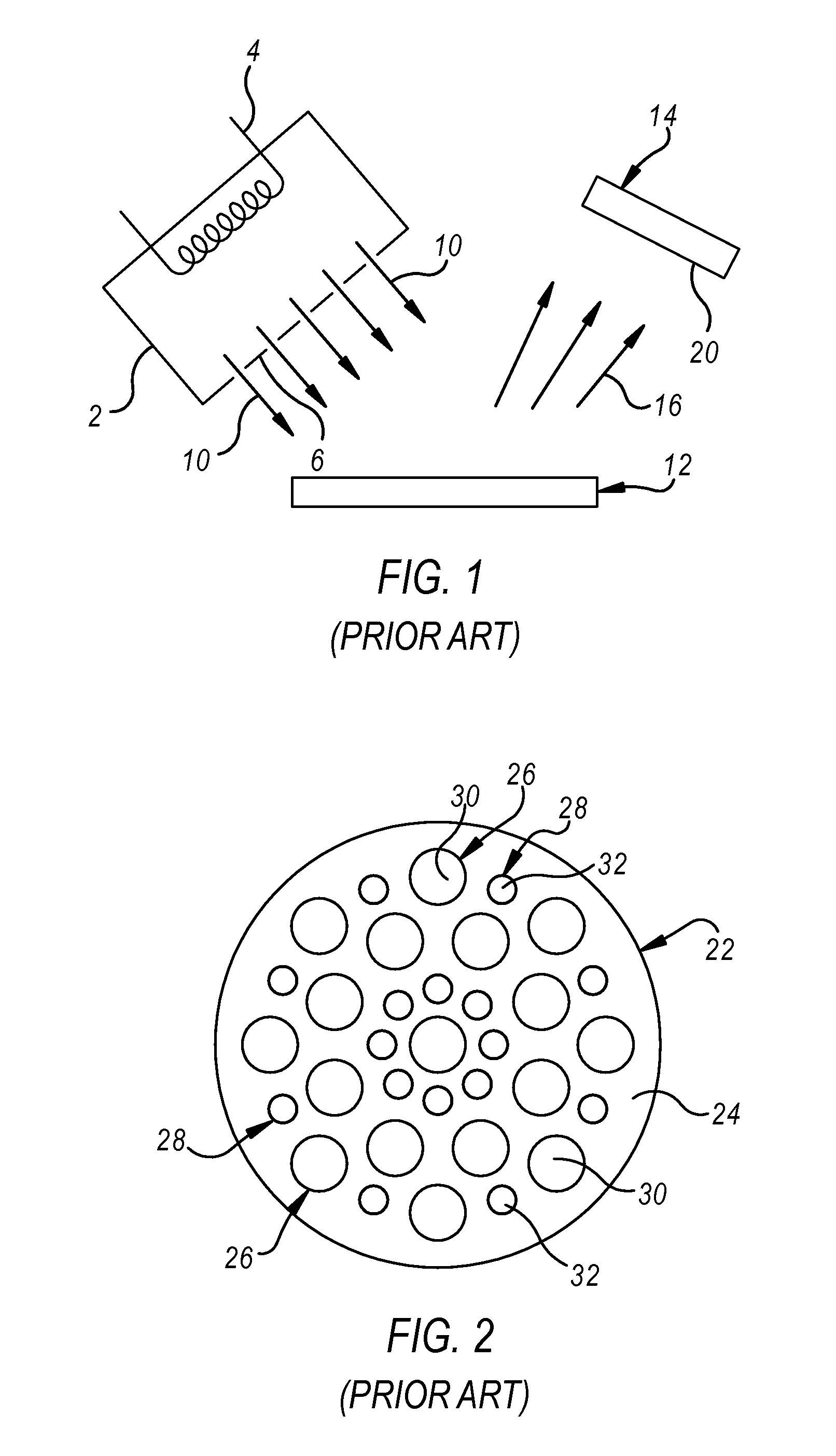
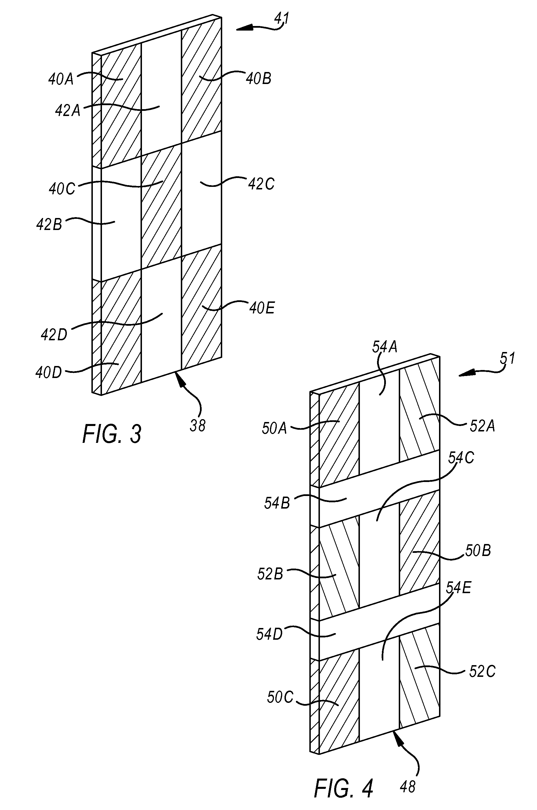
[0022]Referring now to the discussion that follows and also to the drawings, illustrative approaches to the disclosed systems and methods are shown in detail. Although the drawings represent some possible approaches, the drawings are not necessarily to scale and certain features may be exaggerated, removed, or partially sectioned to better illustrate and explain the present disclosure. Further, the descriptions set forth herein are not intended to be exhaustive or otherwise limit or restrict the claims to the precise forms and configurations shown in the drawings and disclosed in the following detailed description.

[0023]Moreover, a number of constants may be introduced in the discussion that follows. In some cases illustrative values of the constants are provided. In other cases, no specific values are given. The values of the constants will depend on characteristics of the associated hardware and the interrelationship of such characteristics with one another as well as environmenta...


PUM

PropertyMeasurementUnit
lengthaaaaaaaaaa
widthaaaaaaaaaa
thicknessaaaaaaaaaa

Abstract

A target for use in an ion beam sputtering apparatus made of at least two target tiles where at least two of the target tiles are made of different chemical compositions and are mounted on a main tile and geometrically arranged on the main tile to yield a desired chemical composition on a sputtered substrate. In an alternate embodiment, the tiles are of varied thickness according to the desired chemical properties of the sputtered film. In yet another alternate embodiment, the target is comprised of plugs pressed in a green state which are disposed in cavities formed in a main tile also formed in a green state and the assembly can then be compacted and then sintered.

Description

TECHNICAL FIELD[0001]A disclosed target for use in an ion beam sputtering apparatus is made of a plurality of tiles having at least two different chemical compositions. In an alternate embodiment, plugs of a first green state material are inserted into cavities formed in a target tile of a second green state material and then sintered to form a target.BACKGROUND ART[0002]In general, the ion beam sputtering process involves the use of a low energy plasma source in a magnetic field which develops a neutralized ion beam with the ion energy, direction and current density all independently controllable and all independent of the type of target used. The plasma is produced by direct current electron bombardment of a low pressure gas, typically inert, but which may have a small percentage of reactive gases.[0003]Generally, any target material which can be physically placed in a vacuum chamber can be sputtered by this process. This includes powders and composite targets, as well as elementa...

Claims


Application Information

Patent Timeline
08 Dec 2011
Publication
US20110297535A1
IPC
C23C14/34; B32B38/00
CPC
C23C14/3407; C23C14/46; C23C14/3414
Inventors
HIGDON, CLIFTON; ELMOURSI, ALAA A.