Durable small gauge wire electrical conductor suitable for delivery of high intensity energy pulses

a small gauge, electrical conductor technology, applied in the direction of internal electrodes, transvascular endocardial electrodes, therapy, etc., can solve the problems of high pressure, no left, and the number of probes has not been successful in accessing the heart wall, and achieves high redundancy for each connection, high flexibility, and increased flexibility of leads

Inactive Publication Date: 2011-12-08
CARDIA ACCESS
View PDF4 Cites 27 Cited by
  • Summary
  • Abstract
  • Description
  • Claims
  • Application Information

AI Technical Summary

Benefits of technology

[0016]In a further embodiment the center of the fiber core is hollow to increase flexibility of a lead of a given diameter. In still a further embodiment, multiple conductors are embedded separately side-by-side in the glass fiber core, where the glass serves to electrically insulate the conductors from each other.
[0017]In an additional embodiment, an electrical conductor is composed of many smaller metal-buffered or metal wire-centered glass fibers that together provide the electrical connection. This embodiment allows for high redundancy for each connection and very high flexibility.
[0018]Additional embodiments differ from the aforementioned embodiments in that metal is not necessarily applied directly to the glass fiber. As mentioned previously, a non-metal buffer such as carbon and / or polymer may be applied directly to the glass fiber core to form a protective hermetic seal layer on the fiber. Metal can then be deposited upon the carbon and / or polymer in a subsequent step. Such a metal deposition process may conveniently take place through a batch process, or via a continuous deposition process, in which carbon- and / or polymer-coated fiber is moved continuously through a deposition chamber during the metal deposition process. Such metal deposition may be carried out by vapor deposition, electroplating—especially upon an electrically conductive carbon surface, by coating with an electrically conductive ink, or by one of numerous other metal deposition processes known in the art. In the case of vapor deposition and related processes governed by line-of-sight considerations, one or more metal targets—sources for vaporized metal, may be positioned within the metal deposition chamber in such a way as to insure overlap and complete 360 degree coverage of the fiber during the metal deposition process. Alternately, the fiber may be turned or rotated within the vapor deposition field to insure complete and uniform deposition. Vapor deposition processes are typically carried out in an evacuated chamber at low atmospheric pressure (approximately 1.0×10⁻⁶ torr). After evacuation is attained, the chamber is backfilled with a plasma-forming gas, typically argon, to a pressure of 2.0×10⁻³ torr. Masking may be pre-applied to the carbon and / or polymer surface to enable a patterned coating of metal on the carbon and / or polymer surface. Such a pattern may be useful for creating two or more separate electrically conductive paths along the length of the electrical conductor, thus enabling fabrication of a bipolar or multipolar conductor upon a single electrical conductor. Inherent in the concept of a metallized electrical conductor according to this invention is the ability to use more than one metal in the construction of such electrical conductors. For instance, an initial metal may be deposited on the basis of superior adhesion to the carbon and / or polymer underlayment. One or more additional metals or metal alloys could then be deposited on the first metal. Intent of the second metal would be to serve as the primary conductive material for carrying electrical current.
[0019]The completed metallized electrical conductor may then be conveniently coated with a thin polymeric material, (polytetrafluoroethylene (PTFE) for example) to provide insulation and / or lubriciousness. Also, polyurethane or silicone or other insulative polymers may conveniently be used as jacketing material, providing biocompatibility and protection from the external environment. A coaxial iteration of this embodiment incorporating two independent electrical conductors may be constructed in which a metal electrical conductor is embedded within the central glass or silica core, with the second conductor being applied to the carbon and / or polymer buffer residing on the outer surface of the glass or silica core.

Problems solved by technology

No left, high pressure, heart access through the heart wall has been successful.
This access path has several drawbacks; the placement of the probes is limited to areas covered by veins, and the leads occlude a significant fraction of the vein cross section and the number of probes is limited to 1 or 2.
Previously available wire leads have not withstood these repeated flexings over long periods of time, and many have experienced failure due to the fatigue of repeated bending.
A straight wire can be put in overall tension, leading to fatigue failure, whereas a filar wound cannot.
However, the bulk of the wire and the need to coil or twist the wires to reduce stress, limit the ability to produce smaller diameter leads.
Other non-medical applications may require that electrical conductors function with a great degree of precision and integrity in hostile environments, posing challenges to electrical conductor design that are shared with implantable medical devices.
For instance, electrical conductors deployed in environments where the conductor is exposed to repetitive motion may result in fatigue failure to the conductor, not unlike what can occur with pacemaker or defibrillator leads.
These electrical conductors may also need to operate under conditions in which minimization of size and weight are required in ways that are not met by currently available electrical conductors.

Method used


Image

  • Durable small gauge wire electrical conductor suitable for delivery of high intensity energy pulses
  • Durable small gauge wire electrical conductor suitable for delivery of high intensity energy pulses
  • Durable small gauge wire electrical conductor suitable for delivery of high intensity energy pulses

Examples


Embodiment Construction

[0048]The invention encompasses electrical conductors for all implantable electrostimulation and sensing devices having implanted wire leads, as well as non-medical applications where light weight and durability are important characteristics contributing to the performance of the electrical conductor, especially in extreme environmental conditions. Also necessary is a capability of the lead to withstand physical stresses imposed by passage of high intensity electrical pulses along the conductor.

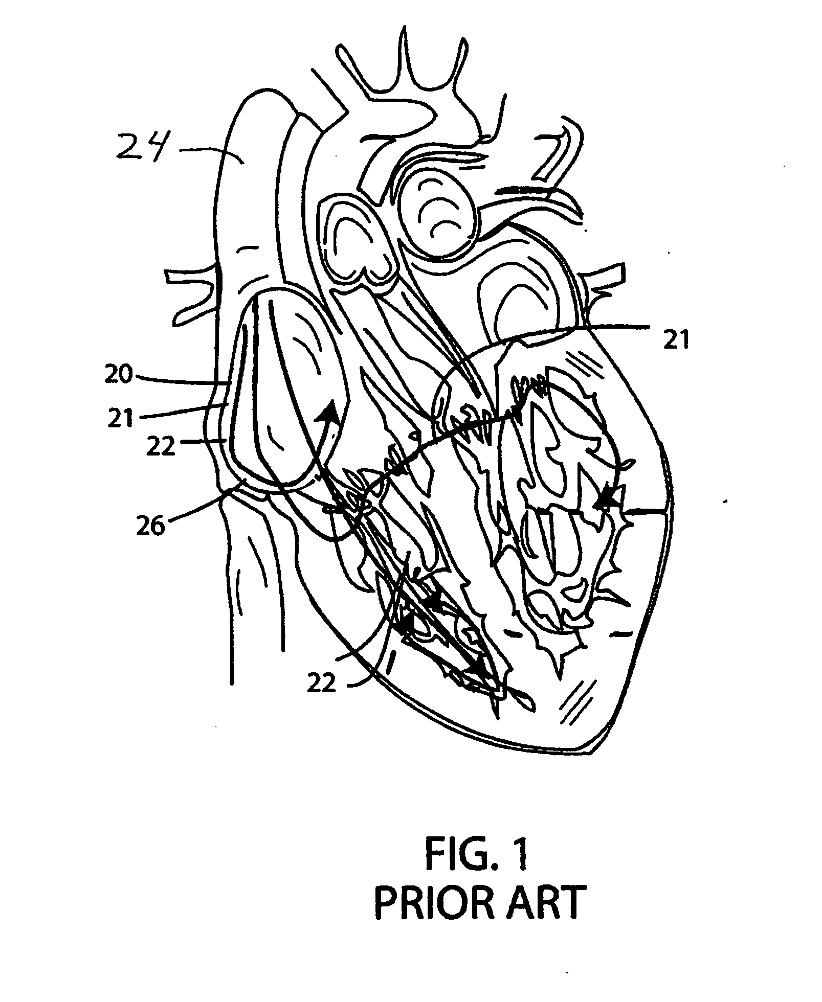
[0049]FIG. 1 shows schematically a human heart with some walls cut away. In FIG. 1 pacing leads are shown following a conventional path into the heart, and into the cardiac veins of the left ventricle, as has been typical of conventional practice and which, with some exceptions, is the basic path of leads of this invention.

[0050]In typical conventional practice, conductive leads 20, 21 and 22 are introduced into the heart through the superior vena cava 24, brought into the vena cava via subcl...


PUM


Abstract

Implantable medical devices intended for electrostimulation and sensing devices typically incorporate one or more electrical conductors as leads for electrical stimulation to, or retrieval of localized sensing data from, discrete points in the body, such as the heart. Certain applications require delivery of high intensity electrical pulses, i.e. CRTs, or defibrillators. As described herein a CRT delivers high energy pulses via a durable fine wire lead formed of a glass, silica, sapphire or crystalline quartz fiber core with a metal coating. A unipolar electrical conductor can have an outer diameter of about 150 microns or even smaller. The buffered fibers support conduction of high intensity electrical pulses as required for internal or external defibrillators, or other biomedical applications, as well as non-medical applications. Defibrillation pulses can be transmitted through less cross-sectional area of metal in the subject fine wire conductor than would be the case with conventional solid core metal wires. Multiple such coated fibers can act as a single conductor. An outer protective sheath of a flexible polymer material can be included.

Description

[0001]This application claims benefit of provisional application Ser. No. 61 / 274,457, filed Aug. 18, 2009. This application also is a continuation-in-part of Ser. No. 12 / 156,129, filed May 28, 2008, now ______, and also a continuation-in-part of application Ser. No. 12 / 590,851, filed Nov. 12, 2009. All of the above applications are incorporated herein by reference.BACKGROUND OF THE INVENTION[0002]This invention concerns a durable small gauge electrical conductor suitable for use in delivery of high intensity energy pulses such as might be required for biomedical applications. The durable fine wire conductor delivers high intensity energy pulses, e.g. 30-35 joules over about 2.5 msec or less, from an electrical pulsing device, typically a capacative discharge device. These biomedical applications may include external and internal cardiac defibrillators (ECDs, ICDs), as well as neurological blocks for pain / sensory or motor control mitigation. Application of the electrical conductor of...

Claims


Application Information

Patent Timeline
Patent Type & Authority Applications(United States)
IPC IPC(8): A61N1/39
CPCA61N1/056
Inventor WALSH, ROBERT G.SHIMADA, JINENGLE, SCOTT
Owner CARDIA ACCESS
Why Eureka
Try Eureka