
X-ray source comprising a field emission cathode

a field emission cathode and x-ray source technology, applied in tomography, instruments, nuclear engineering, etc., can solve the problems of limited control possibilities of x-ray tubes based on thermionic emission, high energy consumption, and inability to meet modern applications, and achieve the effect of increasing efficiency

Inactive Publication Date: 2011-12-15
LIGHTLAB SWEDEN AB
View PDF4 Cites 10 Cited by
  • Summary
  • Abstract
  • Description
  • Claims
  • Application Information

AI Technical Summary

Benefits of technology

The present invention is about an x-ray source that uses a field emission cathode to emit x-rays. The field emission cathode consists of a carbonized solid compound foam with a continuous cellular structure that provides multiple emission cites for emitting electrons in the direction of the anode when a high voltage potential is applied. The use of a field emission cathode allows for better control of the emission of electrons, resulting in higher efficiency and a smaller amount of x-rays emitted. The evacuated chamber of the x-ray source has a pressure of approximately 10−4 Pa or lower for allowing free flow of the emitted electrons. The x-ray source can be easily manufactured and is portable. The invention also includes an x-ray system with the x-ray source and an x-ray detector, an object holder, and a control unit for controlling the x-ray emission and collecting data from the x-ray detector. The system can be portable and battery-operated. The invention also provides a method for scanning an object using the x-ray source. The technical effects of the invention include increased efficiency, portability, and the ability to generate a three-dimensional image of the object.

Problems solved by technology

The use of x-ray tubes based on thermionic emission however provides limited control possibilities, especially due to the fact that such x-ray tubes exhibit a slow reaction time, high energy consumption, and have a high space requirement.
Such x-ray tubes are therefore less suited for the modern applications.
However, the use of such a field emission cathode provides a limiting result as a large extraction current, giving high energy consumption, is needed to achieve a steady emission of electrons.
Thus, due to the high energy consumption such an implementation is undesirable as it limits the mobility of the resulting x-ray system.

Method used


Image

  • X-ray source comprising a field emission cathode
  • X-ray source comprising a field emission cathode
  • X-ray source comprising a field emission cathode

Examples


first embodiment

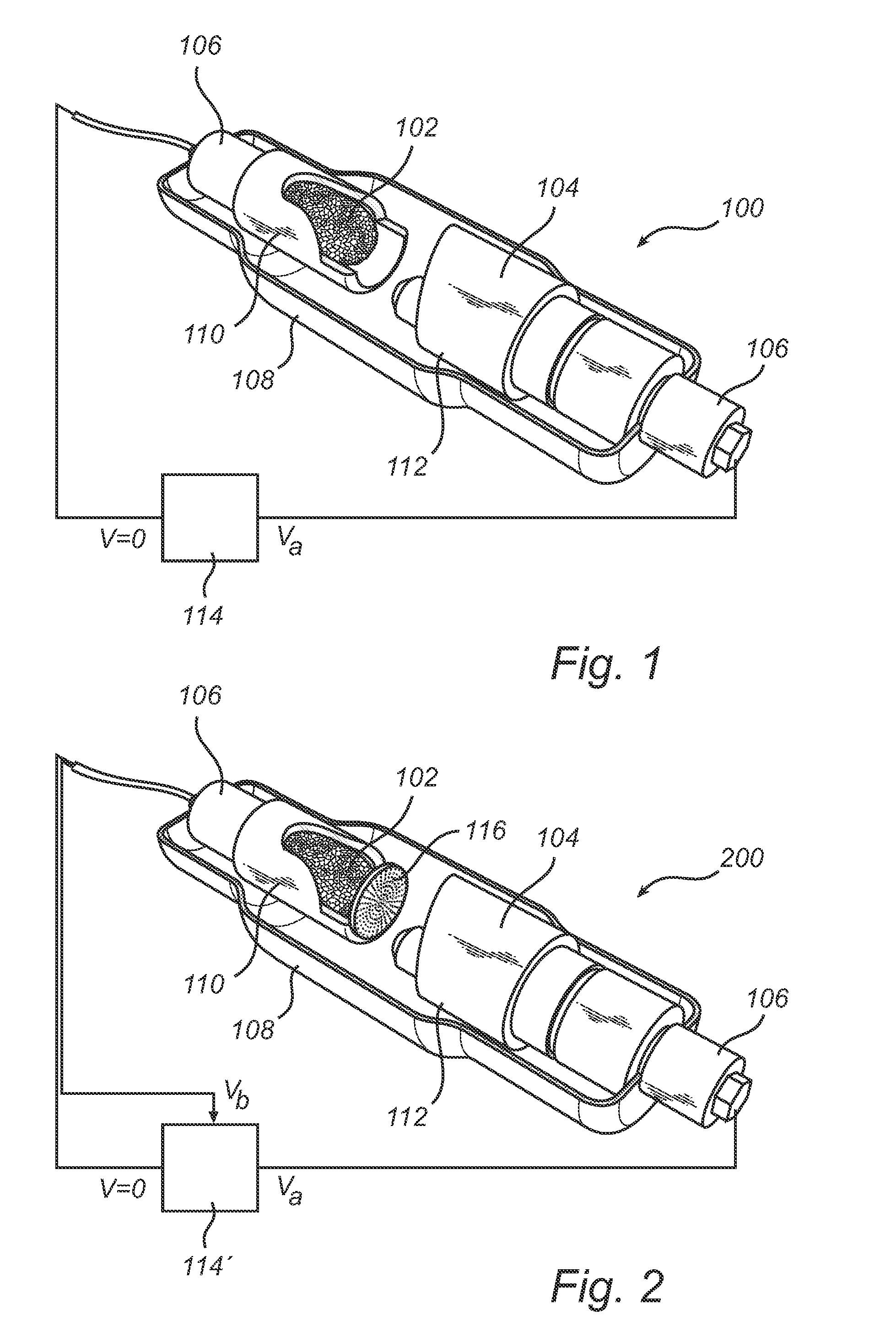
[0026]Referring now to the drawings and to FIG. 1 in particular, there is depicted a conceptual view of an x-ray source 100 according to the present invention. The x-ray source 100 comprises a cathode and an anode (i.e. diode structure), where the cathode is a field emission cathode 102 and the anode preferably is a metal anode 104, for example of copper. Each of the cathode 102 and the anode 104 are provided with an electrical connector 106 which extends out of an evacuated chamber 108, for example of glass or metal, and at least having a window transparent to x-rays when the chamber is of metal. The chamber 108 preferably has a pressure around approximately 10−4 Pa, but could of course depending of the application be more or less. For connecting the cathode 102 and the anode 104 to the electrical connectors 106, each of the cathode 102 and the anode 104 are provided with a holder 110 and 112, respectively.

[0027]The field emission cathode 102 preferably consists of a carbonized sol...

second embodiment

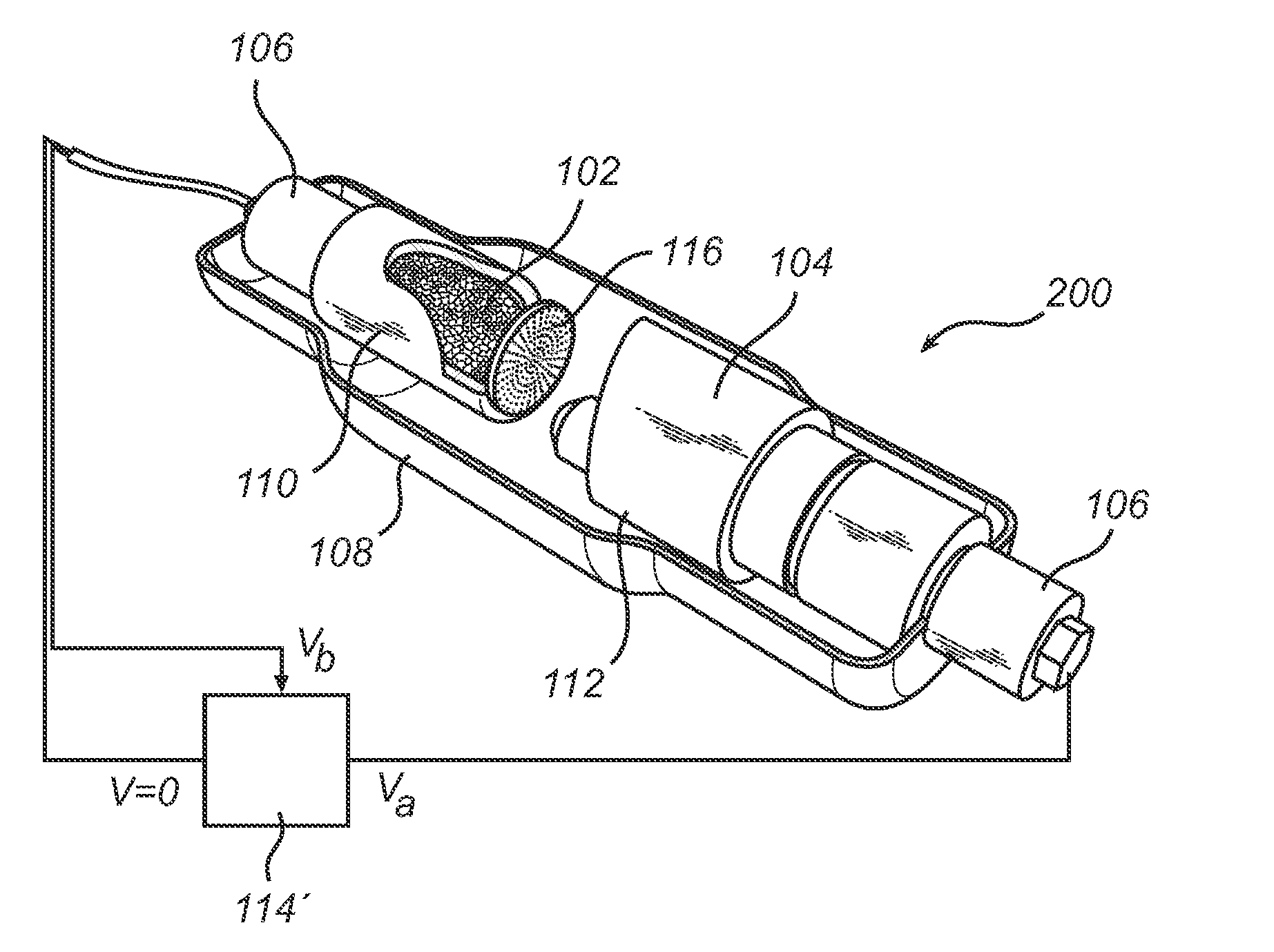
[0029]Turning now to FIG. 2, illustrating a conceptual view of an x-ray source 200 according to the present invention. The x-ray source 200 is essentially similar to the x-ray source 100 of FIG. 1, having a difference in that the x-ray source 200 is of a triode structure, i.e. also comprising a gate electrode 116 arranged at a distance from the field emission cathode 102, preferably in the range of a few tens of micrometers to several millimeters from the surface of the cathode 102 surface. By means of the applying a bias field between gate electrode 116 and the cathode 102, it may be possible to increase the extractions of electrons in the direction of the anode 104. For such an operation, the gate electrode 116 may be connected, through the connector 106, to a slightly modified power supply 114, thereby allowing for the application of a bias voltage for the gate electrode 116. By mean of the triode structure it will be possible to independently at least adjust the current intensit...


PUM

PropertyMeasurementUnit
pressureaaaaaaaaaa
currentaaaaaaaaaa
voltage potentialaaaaaaaaaa

Abstract

The present invention relates to an x-ray source, comprising a field emission cathode, an anode, connectors for allowing application of a high voltage between the cathode and the anode for enabling emission of an x-ray beam, and an evacuated chamber inside of which the anode and the cathode are arranged, the evacuated chamber having an x-ray transparent window, wherein the field emission cathode consists of a carbonized solid compound foam having a continuous cellular structure, the continuous cellular structure providing multiple emission cites for emission of electrons onto the anode when the high voltage is applied. The field emission cathode provides for the possibility to increase the efficiency of the x-ray system as it is possible to in a much higher degree control the electrons emitted by the field emission cathode in terms of switching time, current, kinetic energy and the emission direction.

Description

FIELD OF THE INVENTION[0001]The present invention relates to an x-ray source comprising a field emission cathode. The present invention also relates to a method for scanning an object using a field emission based x-ray source.DESCRIPTION OF THE RELATED ART[0002]Systems for generation of x-ray radiation are used, for example, in medical diagnostics in order to acquire radiographic images or to produce planar images for technical diagnostic applications. In the field of technical diagnostic imaging, x-rays are especially effective at penetrating internal structures of a solid object to be examined, and the images formed by the x-rays that pass there through reveal internal flaws or structural defects of the object. Technical diagnostic x-ray imaging thus provides a valuable quality control inspection tool for evaluating structural aspects of a product during manufacture and over the useful life of the product. This form of diagnostic analysis is advantageous over other types of evalua...

Claims


Application Information

Patent Timeline
Patent Type & Authority Applications(United States)
IPC IPC(8): H01J35/06A61B6/03G01N23/04
CPCH01J35/065H01J2235/068H01J2235/062H01J35/14
Inventor HU, QUI-HONG
Owner LIGHTLAB SWEDEN AB
Learn More