Offshore oil spill remediation and recovery system

a technology for oil spills and recovery systems, which is applied in water cleaning, special-purpose vessels, separation processes, etc., can solve the problems of inaccessible conventional recovery methods, deep water, and inability to meet the recent advances in offshore oil drilling technology, and achieves efficient towed, increased stability and speed, and high viscosity

Inactive Publication Date: 2011-12-22
WEST COAST INVESTMENTS LLC
View PDF8 Cites 9 Cited by
  • Summary
  • Abstract
  • Description
  • Claims
  • Application Information

AI Technical Summary

Benefits of technology

[0018]The successively spaced annular venturi provided at the outlet end of each connected stage accelerate the mixed oil and water flow into the adjacent downstream stage in the flow path defined in the interior core of the water-hydrocarbon separator. Each successive venturi comprises a progressively narrower diameter opening at the inlet end of downstream each stage. Upon acceleration of the input flow to a sufficient velocity, the flow path of oil and water through each stage develops laminar flow. The oil, due to heavier viscosity and the tendency of oil molecules to agglomerate, moves outward and adheres to the surface of the walls of the interior core, where it is drawn off at annular venturi openings defined at the peripheral end of each stage, conducted to a containment port, pumped to the surface, and recovered in tanks. The annular venturi also accelerate the lighter viscosity water into a core flow substantially through the center of the flowpath to a successive stage.
[0020]The present water-hydrocarbon separation system has no moving parts, can be constructed cost effectively, and scaled in size to accommodate major offshore spills and recover significant quantities of submerged oil. In as much as there are no moving parts, and no energy requirement other than the towing vessel, such a system can operate continuously.
[0023]In another aspect, the exterior surface of the cylinder is provided with a series of control surfaces such as vanes and controllable ballast tanks that enable the water-hydrocarbon separator to be maneuvered easily and submerged to a desired depth.
[0024]A buoy stabilizer system enables the hydrocarbon separator to be towed efficiently without undesirable pitch or yaw through subsurface areas where a maximum mass of spilled oil may be located. At extreme depths, the control surfaces aid submerged navigation, and increase stability and speed. On board sensors measure pressure and laminar flow in the hydrocarbon separator core and send corrective output signals to the control surfaces and a control system on the towing ship to maintain or increase speed and / or depth of the tow line so as to optimize laminar flow in the hydrocarbon separator core and maximize recovery of subsurface oil.

Problems solved by technology

Oil spill remediation techniques have failed to keep pace with recent advances in offshore oil drilling technology.
Oil spills, particularly those far offshore, and in deep water, are substantially inaccessible to recovery by conventional methods.
Spills form deep water wells, particularly when the oil aggregates through sedimentation, may not rise to the surface, and may have serious long term consequences for marine life and marine based economies, and adversely impact the food supply derived from the ocean.
Over forty years after the Santa Barbara oil spill, conventional remediation measures remain substantially unchanged and ineffectual, and generally are limited to enclosing floating spilled oil with floating booms, skimming oil off the surface, dispersing oil with chemicals, or soaking it up with straw or other absorbent materials when it reaches the shore.
However, choppy water, ocean waves, and strong winds can make it substantially impossible to use the foregoing conventional methods to contain an offshore oil spill.
Further, due to the density of crude oil and tendency of oil molecules to agglomerate, sinking may occur due to the adhesion of particles of sediment or organic matter to the oil.
Such submerged masses of oil are incapable of being contained, much less recovered, by conventional oil spill remediation technology.
Conventional centrifugal water-oil separators have serious disadvantages when applied to deep-water recovery of spilled oil that remains submerged below the ocean surface.
Such conventional centrifugation systems have serious disadvantages making them inapplicable for offshore recovery of oil in deep water.
The centrifuge devices are mechanically complex and consume considerable energy to rotate the cylindrical container filled with oil and water.
Thus, their form factor would be limited by necessity.
The limited availability of energy offshore, in deep ocean, further would render such devices incapable of performing widespread remediation and recovery of a major, deep water, submerged oil spill.
Submerged oil must be pumped up to such a conventional centrifugal oil-water separator system, thus requiring complex pumping equipment, consuming even more energy in the pumping process, and necessitating additional equipment for underwater containment or entrapment of the oil for pumping.
The amount of energy for such a pumping operation would need to be provided by a surface vessel and would prohibit cost effective separation of oil and sea water.

Method used


Image

  • Offshore oil spill remediation and recovery system
  • Offshore oil spill remediation and recovery system
  • Offshore oil spill remediation and recovery system

Examples


Embodiment Construction

[0030]In the following detailed description of the preferred embodiments, reference is made to the accompanying drawings, which form a part hereof, and in which are shown by way of illustration specific embodiments in which the invention may be practiced. The drawings are heuristic for clarity. It is to be understood that other embodiments may be utilized and structural changes may be made without departing from the scope of the present invention.

[0031]The term “oil” as used in this disclosure should be interpreted broadly to include petroleum or hydrocarbons in all naturally occurring states.

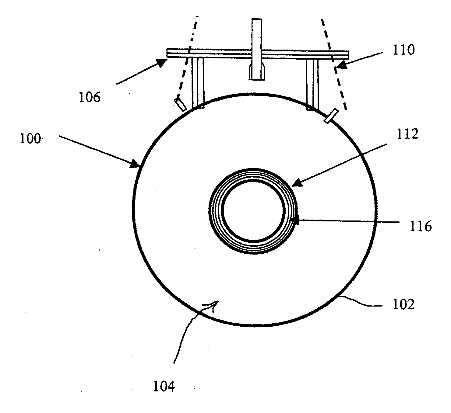
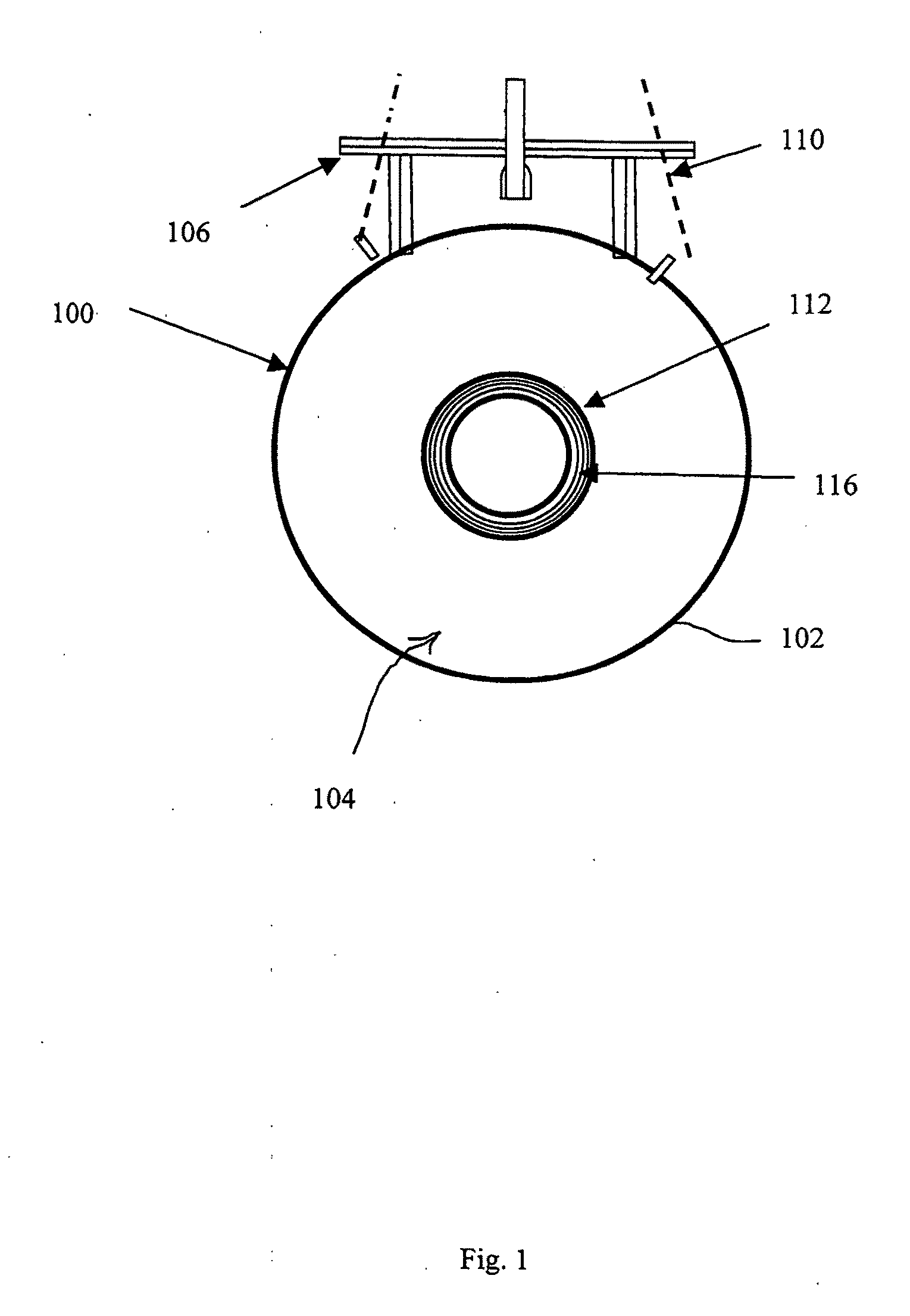
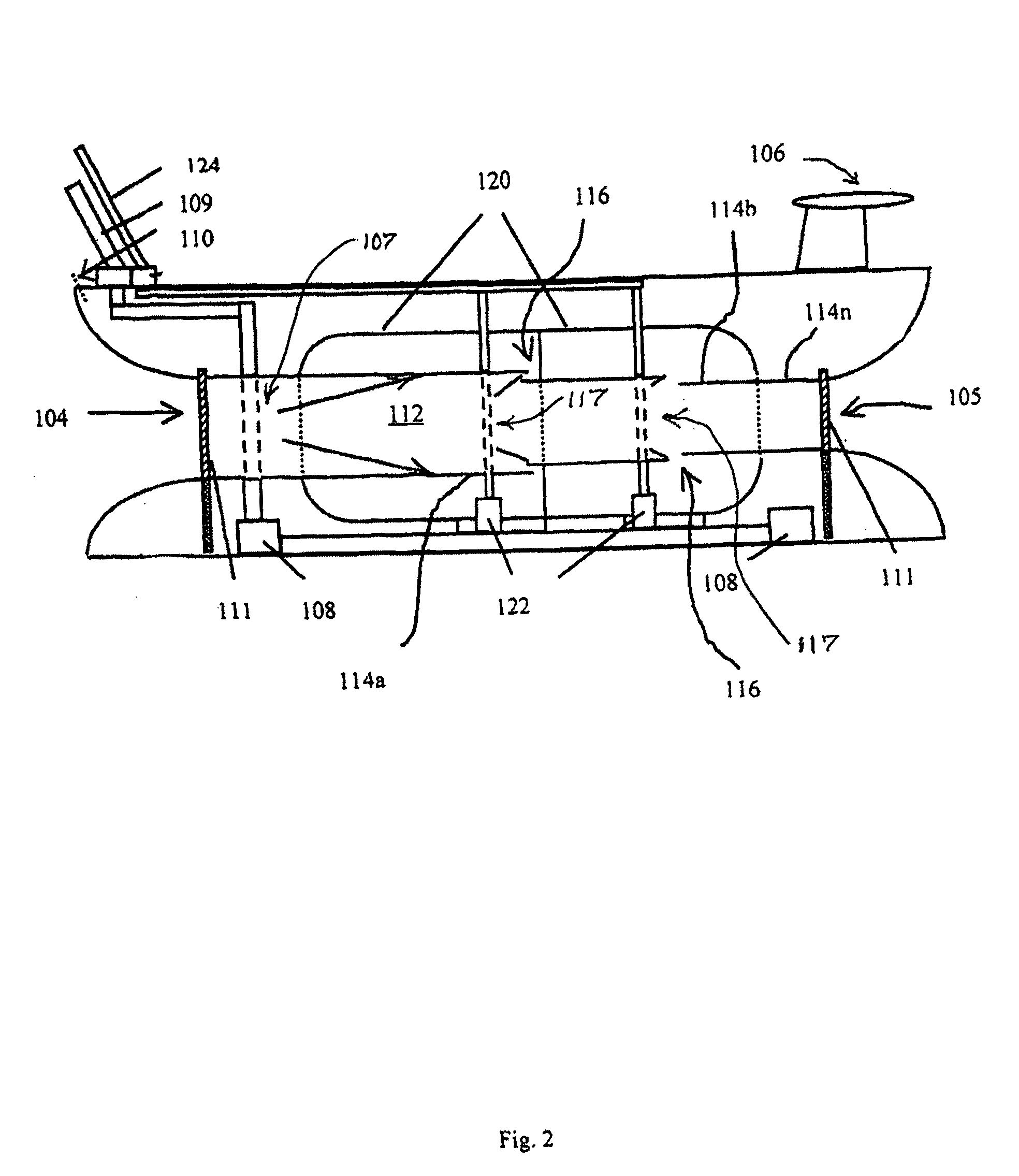
[0032]Referring to FIGS. 1, and 2, an offshore oil spill remediation and hydrocarbon separation system comprises a generally cylindrical vessel 100 having an outer hull 102 defining an inlet 104 for enveloping a submerged mass of oil mixed with seawater and an outlet 105. Vessel 100 is provided with a stabilizer and trim tab assembly 106. The stabilizer and trim assembly operate in a well-known...


PUM

PropertyMeasurementUnit
depthsaaaaaaaaaa
lengthaaaaaaaaaa
velocityaaaaaaaaaa

Abstract

An offshore water-hydrocarbon separator system is capable of entrapping spilled oil offshore, and recovering the oil to a usable state for subsequent refining. The kinetic energy of a towing vessel provides the energy for establishing a flow path of oil and seawater through the hydrocarbon separator. Annular venturi provided at each successive stage in the separator accelerate a core flow of sea water substantially down the center of the flow path, while drag associated with aggregated oil particles forces oil outward, away from the core, to flow along the walls of each stage. The energy that establishes the core flow of water is provided by the kinetic energy of the surface vessel and the acceleration of core flow at each successive venturi. No other source of energy is needed to induce the water hydrocarbon separation.

Description

CROSS REFERENCE TO RELATED APPLICATION[0001]This patent application claims the benefit of U.S. Provisional Application 61 / 397,331 filed Jun. 10, 2010.BACKGROUND[0002]1. Field of the Invention[0003]The field of the invention relates generally to remediation and recovery of useful amounts of oil from offshore oil spills in which crude oil is dispersed, emulsified, aggregated, or otherwise entrained beneath the surface. In particular, the field of the invention relates to a cost effective system for recovery of useful amounts of spilled crude oil through subsurface separation based on the difference in specific gravity between the oil and the sea water.[0004]2. Background of Related Art[0005]Oil spill remediation techniques have failed to keep pace with recent advances in offshore oil drilling technology. Deep-sea drilling technology now exists that enables crude oil extraction at previously unattainable depths. Drilling may be accomplished from an anchored, stable floating deep-sea pl...

Claims


Application Information

Patent Timeline
Patent Type & Authority Applications(United States)
IPC IPC(8): C02F1/40E02B15/04
CPCB01D17/044B01D17/045B01D21/0087C02F1/40B63B35/32C02F2103/007E02B15/046B01D17/041Y10S210/923C02F2101/32Y02A20/204
Inventor HAWTHORNE, NAMON A.
Owner WEST COAST INVESTMENTS LLC
Why Eureka
Try Eureka