

Phosphor ceramic and light-emitting device
a technology of phosphor ceramics and light-emitting devices, which is applied in the direction of transportation and packaging, natural mineral layered products, other domestic articles, etc., can solve the problems of difficult handling of phosphor ceramics, and achieve the effects of improving mechanical strength, easy to ensure light transmission characteristics, and ensuring mechanical strength
- Summary
- Abstract
- Description
- Claims
- Application Information
AI Technical Summary
Benefits of technology
Problems solved by technology
Method used
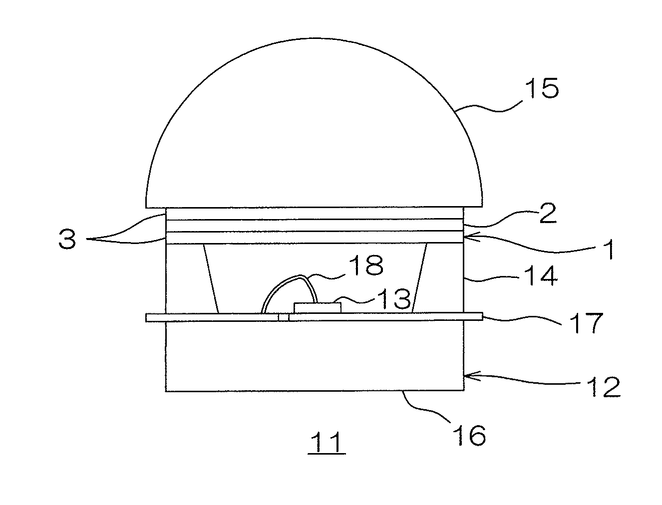
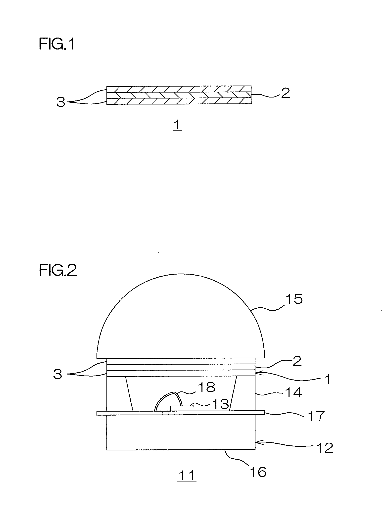
Image

Examples
production example 1
[0088]The components described below were dissolved in 1000 ml of distilled water to prepare 2M (the proportion of Ce atom with respect to Y atom: 1.25 atom %) of a precursor solution. The details of the components were as follows: 283.95 g of yttrium nitrate hexahydrate, 474.62 g of aluminum nitrate enneahydrate, and 4.07 g of cerium nitrate hexahydrate.
[0089]The precursor solution was sprayed and pyrolyzed at a speed of 10 ml / min in RF induction plasma flame using a two-fluid nozzle to obtain precursor particles.
[0090]The crystal phase of the obtained precursor particles was a mixed phase of amorphous and YAP (yttrium aluminum perovskite, YAlO3) crystal when analyzed by an X-ray diffraction method.
[0091]The average particle size of the obtained precursor particles (measured by a BET (Brunauer-Emmett-Teller) method using an automatic surface area analyzer (manufactured by Micrometritics Instrument Corp., model Gemini 2365)) was about 75 nm.
[0092]Next, the obtained precursor particl...
production example 2
[0095]Particles for the fluorescent layer (as described in YAG:Ce-0.5%) were obtained in the same manner as in the above-described Production Example 1 except that the mixing ratio of yttrium nitrate hexahydrate and cerium nitrate hexahydrate was adjusted so that the proportion of Ce atom with respect to Y atom was 0.5 atom %.
production example 3
[0096]Particles for the fluorescent layer (as described in YAG:Ce-0.125%) were obtained in the same manner as in the above-described Production Example 1 except that the mixing ratio of yttrium nitrate hexahydrate and cerium nitrate hexahydrate was adjusted so that the proportion of Ce atom with respect to Y atom was 0.125 atom %.
PUM
| Property | Measurement | Unit |
|---|---|---|
| thickness | aaaaa | aaaaa |
| wavelength | aaaaa | aaaaa |
| wavelength | aaaaa | aaaaa |
Abstract
Description
Claims
Application Information