Dielectric resin composition for film capacitor and film capacitor
a dielectric resin and film capacitor technology, applied in the direction of fixed capacitors, stacked capacitors, fixed capacitor details, etc., can solve the problems of insufficient heat resistance, difficult to produce films with less than 2.5 m thickness, and inconvenient high temperature applications. achieve the effect of improving heat resistance, improving heat resistance of dielectric resin films, and high cohesive energy
- Summary
- Abstract
- Description
- Claims
- Application Information
AI Technical Summary
Benefits of technology
Problems solved by technology
Method used
Image
Examples
experimental example 1
[0042]In Experimental Example 1, comparisons were made at different ratios of acetoacetal groups to benzacetal groups of a polyvinyl acetal.
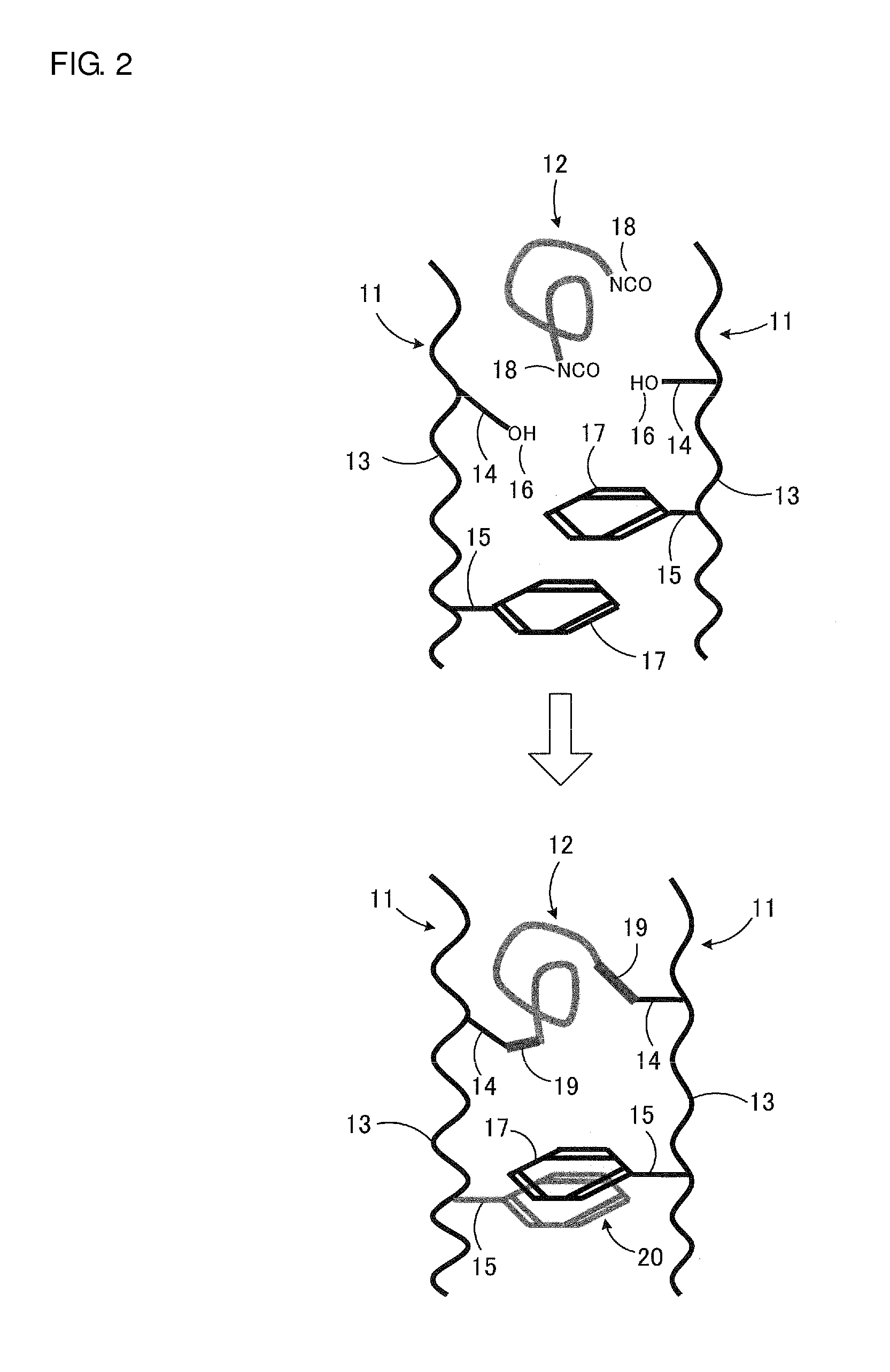
[0043]The method for producing a polyvinyl acetal resin having a benzene ring in its side chain employed included after maintaining an aqueous solution of polyvinyl alcohol at a predetermined temperature, adding benzaldehyde, acetaldehyde, and a catalyst thereto, allowing acetalization to proceed, maintaining the resulting reaction mixture at a predetermined high temperature, and performing neutralization, washing with water, and drying to give a polyvinyl acetal powder (for example, see Japanese Unexamined Patent Application Publication No. 2002-327065 which describes the same reaction without a benzene-containing reactant). The ratio of acetoacetal groups to benzacetal groups in acetal groups in the side chains was adjusted by calculating the ratio of acetoacetal groups to benzacetal groups in a finally synthesized polyvinyl acetal and changin...
experimental example 2
[0055]In Experimental Example 2, comparisons were made between an acetal group and a carbonyl group serving as atomic groups each attached to a side chain of the acetal group.
[0056]In Table 3, the atomic group in the side chain of the acetal group is a benzacetal group in sample 11. This is the same as in sample 4 in Experimental Example 1. In Table 3, sample 12 is the same as sample 11, except that the benzacetal group is replaced with a carbonyl group.
TABLE 3Moleculargroup inBreakdownBreakdownside chainvoltage atvoltage atDielectricof acetalTg25° C.150° C.constantDielectricSamplegroup[° C.][V / μm][V / μm]Handleabilityat 1 kHzloss at 1 kHz11Benzacetal165475475⊙3.60.85group12Carbonyl155450450⊙3.60.85group
[0057]Table 3 demonstrates that sample 12 with the carbonyl group has a glass transition temperature, a breakdown voltage, and handleability comparable to those in sample 11 with the benzacetal group.
experimental example 3
[0058]In Experimental Example 3, comparisons were made at different polyvinyl acetal contents in the cured article. That is, as shown in Table 4, the polyvinyl acetal content was changed in the range of 10% to 100% by weight. Other conditions were the same as those in sample 4 in Experimental Example 1. Thus, sample 24 in Experimental Example 3 is the same as sample 4 in Experimental Example 1.
TABLE 4PolyvinylBreakdownBreakdownacetalvoltage atvoltage atDielectric[% byTg25° C.150° C.constantDielectricSampleweight][° C.][V / μm][V / μm]Handleabilityat 1 kHzloss at 1 kHz21100105225230⊙2.80.822290145400360⊙3.20.822360160430420⊙3.40.832450165475475⊙3.60.852540165475475⊙3.60.842620163450450◯3.70.842710160425425Δ3.70.84
[0059]As is clear from Table 4, excellent results are obtained in samples 22 to 27 each having a polyvinyl acetal content of 10% to 90% by weight. Sample 21 having a polyvinyl acetal content of 100% by weight has a reduced glass transition temperature and a reduced breakdown vol...
PUM
| Property | Measurement | Unit |
|---|---|---|
| temperature | aaaaa | aaaaa |
| operating temperature | aaaaa | aaaaa |
| heat resistance | aaaaa | aaaaa |
Abstract
Description
Claims
Application Information
 - R&D
- Intellectual Property
- Life Sciences
- Materials
- Tech Scout
- Unparalleled Data Quality
- Higher Quality Content
- 60% Fewer Hallucinations
Browse by: Latest US Patents, China's latest patents, Technical Efficacy Thesaurus, Application Domain, Technology Topic, Popular Technical Reports.
© 2025 PatSnap. All rights reserved.Legal|Privacy policy|Modern Slavery Act Transparency Statement|Sitemap|About US| Contact US: help@patsnap.com


