Amplifying device for condenser microphone

a technology of condenser microphone and amplifier, which is applied in the direction of amplifier protection circuit arrangement, amplifier with semiconductor devices/discharge tubes, transducer details, etc., can solve the problem of electric potential change between the diaphragm and the electrode, and achieve the effect of improving the tolerance of esd

Inactive Publication Date: 2012-01-19
PANASONIC CORP
View PDF9 Cites 12 Cited by
  • Summary
  • Abstract
  • Description
  • Claims
  • Application Information

AI Technical Summary

Benefits of technology

[0025]The present invention is configured as described above which provides advantageous effects that the input impedance can be set at from several GΩ to several tens of GΩ, and that the ESD tolerance is improved in the condenser-microphone amplifying device.

Problems solved by technology

Because of this configuration, displacement of the diaphragm causes a change in electrostatic capacitance between the diaphragm and the electrode, thereby consequently causing a change in electric potential between the diaphragm and the electrode.

Method used


Image

  • Amplifying device for condenser microphone
  • Amplifying device for condenser microphone
  • Amplifying device for condenser microphone

Examples


first embodiment

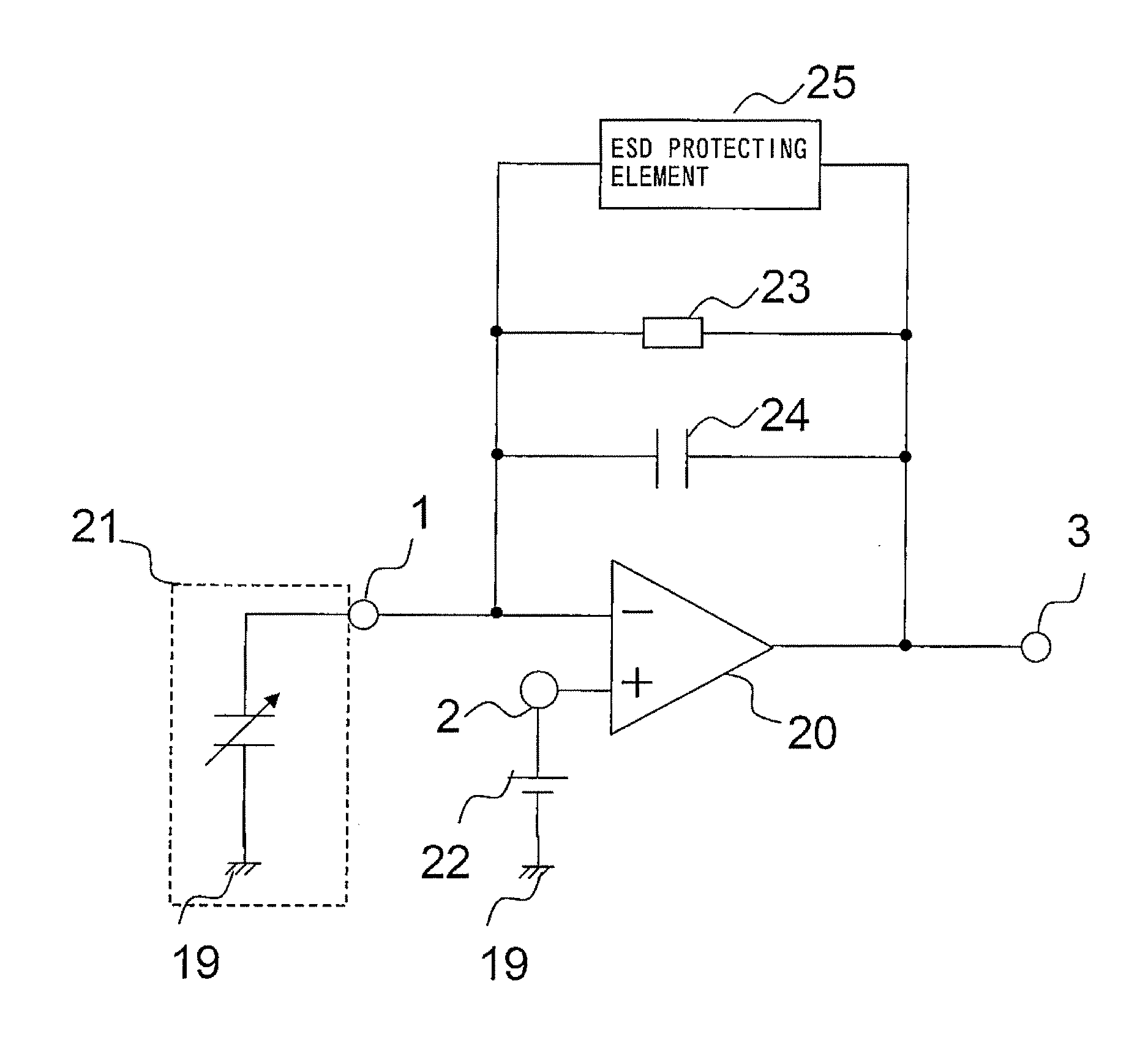
[0037]FIG. 1 is a circuit diagram showing the configuration of a condenser-microphone amplifying device according to a first embodiment of the present invention.

Configuration

[0038]As shown in FIG. 1, the condenser-microphone amplifying device of the first embodiment is provided with a differential amplifier 20 as an amplifying element. The differential amplifier 20 is constituted, for example, by an operational amplifier. The following description will be given taking, by way of example, the case where the differential amplifier 20 is constituted by an operational amplifier. An inverting input terminal 1 of the operational amplifier 20 is connected to a condenser microphone 21. The condenser microphone 21 is constituted, for example, by an ECM, an MEMS microphone, a commonly-used condenser microphone or other like microphone. Hereinafter, the description will be given taking, by way of example, the case where the condenser microphone 21 is constituted by an ECM. A sound pressure sig...

example configuration

of Operational Amplifier

[0044]FIG. 4 is a circuit diagram showing an example of the configuration of the operational amplifier in the condenser-microphone amplifying device of FIG. 1.

[0045]As shown in FIG. 4, the operational amplifier 20 comprises, for example, a differential amplifying unit 51 which differentially amplifies a pair of input voltages Vin1 and Vin2 corresponding to a differential input ΔVin; a differential outputting unit 52 which outputs a differential αΔVin between a pair of output voltages from the differential amplifying unit 51; a gate voltage setting unit 53 by which the transistors forming the differential outputting unit 52 are operated in the active region; and an outputting unit 54 which amplifies the output αΔVin of the differential outputting unit 52 and then outputs it from the output terminal 3.

[0046]In the differential amplifying unit 51, a first current source 15 is connected to a power supply 18; the source of a first P-channel MOS transistor 4 is con...

second embodiment

[0068]FIG. 7 is a circuit diagram showing the configuration of a condenser-microphone amplifying device according to a second embodiment of the present invention.

[0069]As shown in FIG. 7, in the condenser-microphone amplifying device of the second embodiment, the ESD protecting element 25 is constituted by a pair of diode-connected, N-channel MOS transistors 28 and 29, other than which the condenser-microphone amplifying device of the second embodiment is the same as the condenser-microphone amplifying device of the first embodiment.

[0070]More specifically, the ESD protecting element 25 is constituted by the pair of the N-channel MOS transistors 28 and 29 wherein the drain of the one N-channel MOS transistor 28 and the source of the other N-channel MOS transistor 29 are connected together while on the other hand, the source of the one N-channel MOS transistor 28 and the drain of the other N-channel MOS transistor 29 are connected together. Each of the N-channel MOS transistors 28 an...


PUM


Abstract

An amplifying device for a condenser-microphone according to the present invention includes: a differential amplifier (20) having an inverting input terminal (1) to which a sound pressure signal output from a condenser microphone (21) is input and a non-inverting input terminal (2) to which a dc bias voltage is applied; a capacitor (24) connected between an output terminal (3) of the differential amplifier (20) and the inverting input terminal (1) of the differential amplifier (20); a resistive element (23) connected, in parallel with the capacitor (24), between the output terminal (3) of the differential amplifier (20) and the inverting input terminal (1) of the differential amplifier (20); and an ESD protecting element (25) having bidirectional diode characteristics, the ESD protecting element (25) being connected, in parallel with the capacitor (24), between the output terminal (3) of the differential amplifier (20) and the inverting input terminal (1) of the differential amplifier (20).

Description

TECHNICAL FIELD[0001]The present invention relates to amplifying devices for condenser microphones and more particularly relates to condenser-microphone amplifying devices with ESD (electrostatic discharge) protection functions.BACKGROUND ART[0002]Capacitive signal sources such as sound pressure sensors have been known as signal sources having high internal impedances. Condenser microphones have been known as a typical example of the sound pressure sensor which is a capacitive signal source. A condenser microphone is configured such that with a diaphragm and an electrode arranged face to face with each other, an external voltage is applied to the electrode to charge it. Because of this configuration, displacement of the diaphragm causes a change in electrostatic capacitance between the diaphragm and the electrode, thereby consequently causing a change in electric potential between the diaphragm and the electrode. By taking out such an electric potential change as an electric signal,...

Claims


Application Information

Patent Timeline
Patent Type & Authority Applications(United States)
IPC IPC(8): H04R3/00
CPCH03F1/52H03F3/181H03F3/45183H04R3/00H03F2200/444H03F2203/45518H03F2203/45526H03F3/45475
Inventor NAKAYAMA, KAZUYAMASAI, SHIGEO
Owner PANASONIC CORP
Why Eureka
Try Eureka