High strength steel pipe for low-temperature usage having excellent buckling resistance and toughness of welded heat affected zone and method for producing the same
Active Publication Date: 2012-01-26
JFE STEEL CORP
6 Cites 25 Cited by
AI-Extracted Technical Summary
Problems solved by technology
Thus, in high strength steel, the influence of addition of B on the toughness of welded heat affected zones is not sufficiently understood.
However, deformability of base material is not studied in JP '961.
Thus, a steel...
View moreBenefits of technology
[0038]We also provide an APIX100-grade high strength steel pipe for low-temperature usage, the steel pipe having a wall thickness of 20 mm or more, being excellent in terms of buckling r...
View moreAbstract
An APIX100-grade high strength steel pipe includes a base material containing, in mass percentage, C: more than 0.03% and 0.08% or less, Si: 0.01% to 0.5%, Mn: 1.5% to 3.0%, P: 0.015% or less, S: 0.005% or less, Al: 0.01% to 0.08%, Nb: 0.005% to 0.025%, Ti: 0.005% to 0.025%, N: 0.001% to 0.010%, O: 0.005% or less, and B: 0.0003% to 0.0020%, further contains one or more of Cu, Ni, Cr, Mo, and V, satisfies 0.19≦Pcm≦0.25, the balance being Fe and unavoidable impurities, and has a TS of 760 to 930 MPa, a uniform elongation of 5% or more, and a YR of 85% or less; the seam weld metal has a specific composition.
Application Domain
Technology Topic
Image
Examples
- Experimental program(2)
Example
Example 1
[0155]Steels having various chemical compositions in Table 1 were refined with a steel converter and turned into cast slabs having a thickness of 170 to 250 mm by continuous cast. The cast slabs were then turned into steel plates 1 to 10 under conditions of hot rolling, accelerated cooling, and reheating in Table 2. The reheating was performed with an induction heating apparatus disposed together with accelerated cooling equipment on the same line.
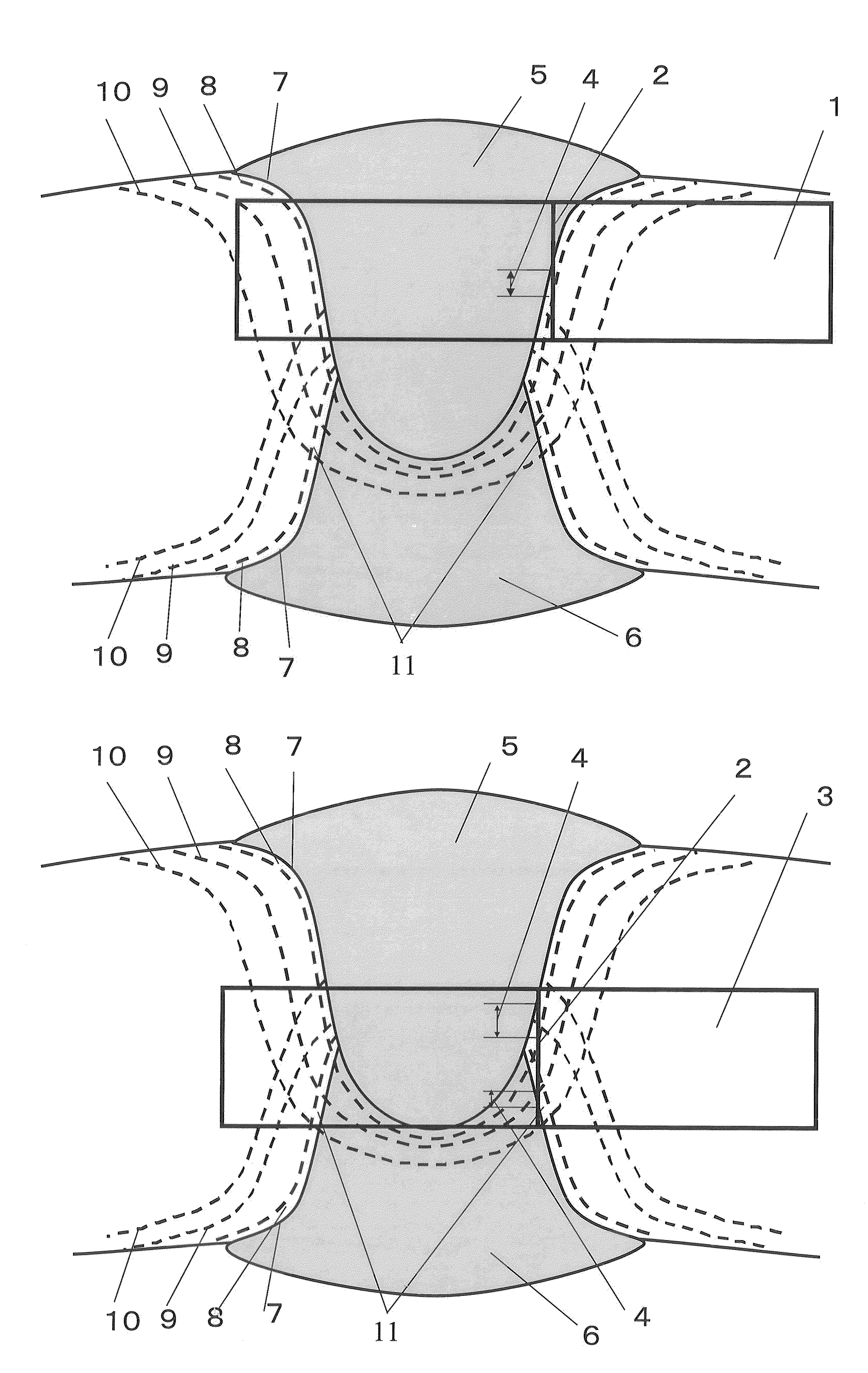
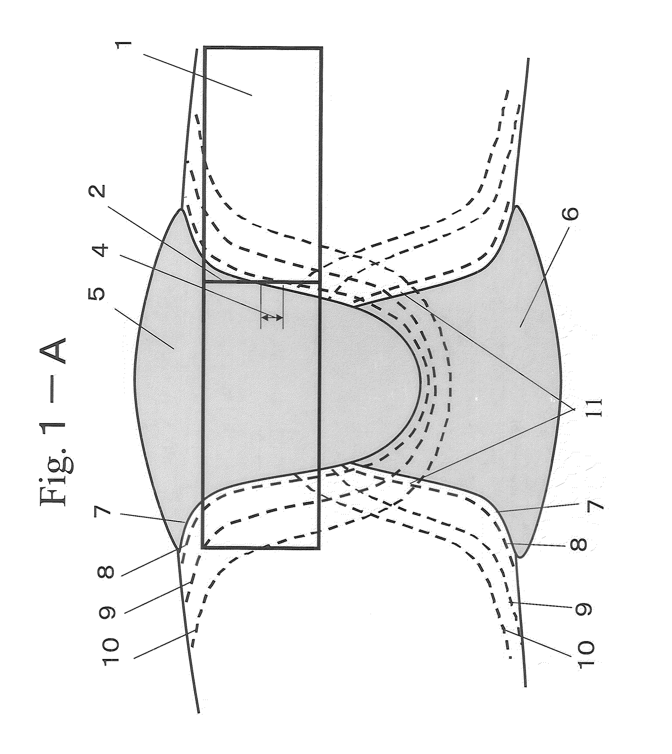
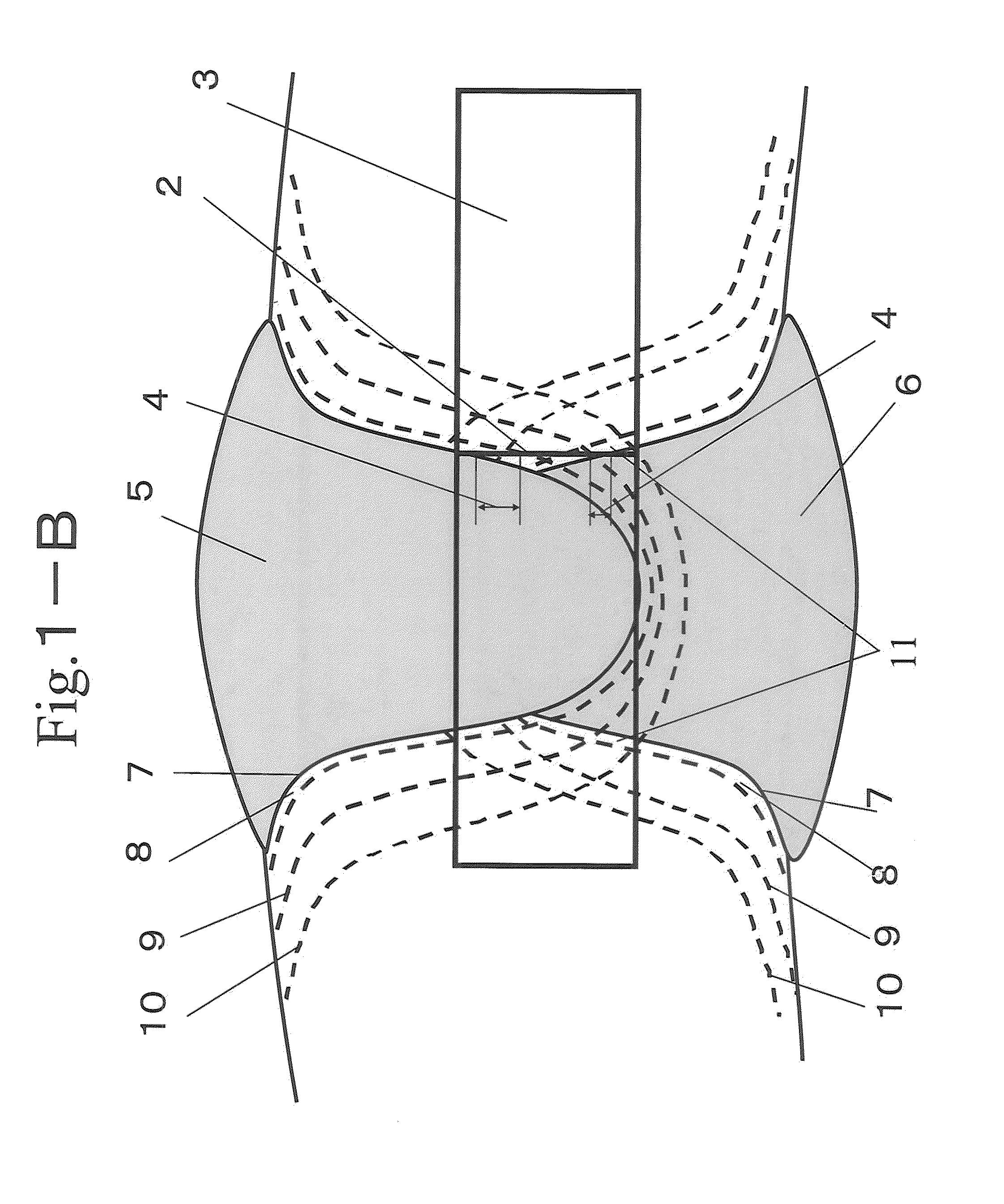
[0156]The steel plates were formed by U-press and O-press and subsequently subjected to internal seam welding then to external seam welding by submerged arc welding. After that, pipe expansion was performed at an expansion ratio of 0.6% to 1.2% to provide steel pipes having an outer diameter of 400 to 1626 mm. Tables 3-1 and 3-2 show the chemical compositions of weld metal portions 6 and 5 for internal seam welding and external seam welding in the steel pipes 1-1 to 10.
[0157]To evaluate the joint strength of the obtained steel pipes, tensile tests were performed with through-thickness tensile specimens in compliance with API-5L that were sampled in the pipe axial direction in terms of base material portions and in the pipe circumferential direction in terms of seam weld portions.
[0158]Charpy impact tests were performed at a test temperature of −30° C. with V-notch charpy impact specimens 1 and 3 according to JIS Z2202 (1980) that were sampled from weld joint portions of the steel pipes at two positions of the external FL position and the Root-FL position illustrated in FIGS. 1-A and 1-B. Note that a notch position 2 was a position where HAZ and weld metal were present with a ratio of 1:1.
[0159]As for the microstructure of CGHAZ, a coarse-grain HAZ (CGHAZ) by external seam welding was observed at positions that were 6 mm away from the surface with an electron scanning microscope (magnification ratio: 5000). The test results of the hardness of coarse-grain HAL (CGHAZ) and the toughness of coarse-grain HAZ (CGHAZ) (hereafter, referred to as HAZ toughness) are summarized in Tables 4-1 and 4-2.
[0160]Charpy impact tests were performed at a test temperature of −40° C. with V-notch charpy impact specimens according to JIS Z2202 (1980) that were sampled from positions in the middle of the plate thickness of base material portions of the steel pipes. In addition, tests were performed at a test temperature of −20° C. with DWTT specimens in compliance with API-5L that were sampled from the steel pipes to thereby determine SA values (shear area, ductile fracture surface area ratio).
[0161]Target conditions are defined as follows: in a base steel plate, a tensile strength is 760 MPa or more and 930 MPa or less, a uniform elongation is 5% or more, and a ratio of 0.5% proof strength to tensile strength is 85% or less; in the base material, a charpy absorbed energy at a test temperature of −40° C. is 210 J or more in a case where the plate thickness is less than 25 mm and is 150 J or more in a case where the plate thickness is 25 mm or more, and DWTTSA-20° C. is 85% or more; the seam weld joint strength of a steel pipe is 760 MPa or more and 930 MPa or less; and, in the above-described coarse-grain HAZ (CGHAZ), a charpy absorbed energy at a test temperature of −30° C. is 100 J or more.
[0162]Tables 4-1 and 4-2 show the test results. Test Nos. 1, 2, and 3 are inventive examples: each base material portion had desired strength, yield ratio, uniform elongation, and toughness; each seam weld portion had high HAZ toughness; the microstructure of the base material portion was mainly constituted by a bainite structure containing island martensite having an area fraction of 4% or more and 12% or less, the island martensite contained had a long axis size of 2 μm or less, and bainitic ferrite surrounded by boundaries having a misorientation of 15° or more had a long axis size of 20 μm or less.
[0163]In addition, the microstructure of a coarse-grain HAZ (CGHAZ) was a multi-phase structure containing lower bainite having an area fraction of 50% or more, the balance being upper bainite and/or martensite.
[0164]In contrast, as for test Nos. 4, 5, and 6, the base material compositions were adequate, but the cumulative rolling reduction at 750° C. or less in the rolling of steel plates was less than 75% (refer to Table 2) and, as a result, the toughness of the base materials was poor. The microstructures of the weld portions satisfied the definitions and had good toughness.
[0165]As for test Nos. 7, 8, and 9, the base material compositions were in our range, but the welding heat input was high. Thus, in the microstructures of the coarse-grain HAZ (CGHAZ) of the joints, the fraction of lower bainite was below the lower limit of the definition and the fraction of an upper bainite structure was high. Accordingly, HAZ toughness was poor in the external and internal Root zones.
[0166]As for test No. 10, B was not added and the fraction of an upper bainite structure was high. Accordingly, HAZ toughness was poor in the external and internal Root zones.
[0167]As for test No. 11, the PCM was below our lower limit and the base material and the joint had a tensile strength of less than 760 MPa. In addition, in the microstructure of the coarse-grain HAZ (CGHAZ) of the joint, the fraction of lower bainite was low and the coarse-grain HAZ (CGHAZ) structure was an upper bainite structure. Accordingly, HAZ toughness was poor in the external and internal Root zones.
[0168]As for test No. 12, the PCM value was beyond our upper limit and the coarse-grain HAZ (CGHAZ) structure was a martensite structure. Accordingly, HAZ toughness was poor in the external and internal Root zones.
[0169]As for test No. 13, although internal welding heat input and external welding heat input were 80 kJ/cm or less, the internal welding heat input was higher than the external welding heat input. Thus, the microstructure of the Root zone in which austenite grain size was large was subjected to rapid cooling and hence a coarse upper bainite structure was formed. Accordingly, Root HAZ toughness was poor.
Example
Example 2
[0170]Steels having various chemical compositions in Table 5 were refined with a steel converter and turned into cast slabs having a thickness of 160 to 250 mm by continuous cast. The cast slabs were then turned into steel plates 11 to 24 under conditions of hot rolling, accelerated cooling, and reheating in Table 6. The reheating was performed with an induction heating apparatus disposed together with accelerated cooling equipment on the same line.
[0171]The steel plates were formed by U-press and O-press and subsequently subjected to internal seam welding then to external seam welding by submerged arc welding. After that, pipe expansion was performed at an expansion ratio of 0.6% to 1.2% to provide steel pipes having an outer diameter of 400 to 1626 mm. Tables 7-1 and 7-2 show the chemical compositions of weld metal portions for internal seam welding and external seam welding of the steel pipes 11-1 to 24.
[0172]To evaluate the joint strength of the obtained steel pipes, tensile tests were performed with through-thickness tensile specimens in compliance with API-5L that were sampled in the pipe axial direction in terms of base material portions and in the pipe circumferential direction in terms of seam weld portions.
[0173]Charpy impact tests were performed at a test temperature of −30° C. with V-notch charpy impact specimens 1 and 3 according to JIS Z2202 (1980) that were sampled from weld joint portions of the steel pipes at two positions of the external FL position and the Root-FL position illustrated in FIGS. 1-A and 1-B. Note that a notch position 2 was a position where HAZ and weld metal were present with a ratio of 1:1.
[0174]As for the microstructure of CGHAZ, a coarse-grain HAZ (CGHAZ) by external seam welding was observed at positions that are 6 mm away from the surface with an electron scanning microscope (magnification ratio: 5000). The test results of the hardness of coarse-grain HAZ (CGHAZ) and the toughness of coarse-grain HAZ (CGHAZ) (hereafter, referred to as HAZ toughness) are summarized in Tables 8-1 and 8-3.
[0175]Charpy impact tests were performed at a test temperature of −40° C. with V-notch charpy impact specimens according to JIS Z2202 (1980) that were sampled from positions in the middle of the plate thickness of base material portions of the steel pipes. In addition, tests were performed at a test temperature of −20° C. with DWTT specimens in compliance with API-5L that were sampled from the steel pipes to thereby determine SA values (shear area, ductile fracture surface area ratio).
[0176]Our target conditions are defined as follows: in a base steel plate, a tensile strength is 760 MPa or more and 930 MPa or less, a uniform elongation is 5% or more, and a ratio of 0.5% proof strength to tensile strength is 85% or less; in the base material, a charpy absorbed energy at a test temperature of −40° C. is 210 J or more in a case where the plate thickness is less than 25 mm and is 150 J or more in a case where the plate thickness is 25 mm or more, and DWTTSA-20° C. is 85% or more; the seam weld joint strength of a steel pipe is 760 MPa or more and 930 MPa or less; and, in the above-described coarse-grain HAZ (CGHAZ), a charpy absorbed energy at a test temperature of −30° C. is 1001 or more.
[0177]The produced steel plates were subjected to a strain ageing treatment by being held at 250° C. for 30 minutes. After that, evaluation was similarly performed by subjecting the base materials to tensile tests and Charpy tests and subjecting the welded heat affected zones (HAZ) to Charpy tests. The evaluation criteria used after the strain ageing treatment were the same as the above-described evaluation criteria used before the strain ageing treatment.
[0178]Tables 8-1, 8-2, 8-3, and 8-4 show the test results. Test Nos. 14, 15, 16, 17 and 18 are inventive examples in which base materials and weld portions satisfied our definitions: each base material portion had desired strength, yield ratio, uniform elongation, and toughness; each seam weld portion had high HAZ toughness; the microstructure of the base material portion was mainly constituted by a bainite structure containing island martensite having an area fraction of 4% or more and 12% or less, the island martensite contained had a long axis size of 2 μm or less, and bainitic ferrite surrounded by boundaries having a misorientation of 15° or more had a long axis size of 20 μm or less.
[0179]In addition, the microstructure of a coarse-grain HAZ (CGHAZ) was a multi-phase structure containing lower bainite having an area fraction of 50% or more, the balance being upper bainite and/or martensite.
[0180]In contrast, as for test Nos. 19, 20, 21 and 22, the base material compositions were adequate, but the cumulative rolling reduction at 750° C. or less in the rolling of steel plates was less than 75% (refer to Table 6) and, as a result, the toughness of the base materials was poor. The microstructures of the weld portions satisfied our definitions and had good toughness.
[0181]As for test Nos. 23, 24, 25, and 26, the base material compositions were in our range, but the welding heat input was high. Thus, in the microstructures of the coarse-grain HAZ (CGHAZ) of the joints, the fraction of lower bainite was below the lower limit of our definition and the fraction of an upper bainite structure was high. Accordingly, HAZ toughness was poor in the external and internal Root zones.
[0182]As for test No. 27, B was not added and the fraction of an upper bainite structure was high. Accordingly, HAZ toughness was poor in the external and internal Root zones.
[0183]As for test No. 28, the PCM was below our lower limit and the base material and the joint had a tensile strength of less than 760 MPa. In addition, in the microstructure of the coarse-grain HAZ (CGHAZ) of the joint, the fraction of lower bainite was low and the coarse-grain HAZ (CGHAZ) structure was an upper bainite structure. Accordingly, HAZ toughness was poor in the external and internal Root zones.
[0184]As for test No. 29, the PCM value was beyond our upper limit and the coarse-grain HAZ (CGHAZ) structure was a martensite structure. Accordingly, HAZ toughness was poor in the external and internal Root zones. In addition, the toughness of the base material was poor.
[0185]As for test No. 30, although internal welding heat input and external welding heat input were 80 kJ/cm or less, the internal welding heat input was higher than the external welding heat input. Thus, the microstructure in the Root zone in which austenite grain size was large was subjected to rapid cooling and hence a coarse upper bainite structure was formed. Accordingly, Root HAZ toughness was poor.
[0186]Note that, even after the inventive examples of test Nos. 14 to 18 were subjected to the strain ageing treatment of being held at 250° C. for 30 minutes, they had excellent test results equivalent to those before the strain ageing, in terms of tensile tests and Charpy tests of base materials, Charpy tests of welded heat affected zones (HAZ), and the like. In contrast, in the comparative example of test No. 31, the cooling stopping temperature in the steel plate production was too low and hence the MA fraction required was not achieved. Accordingly, test No. 31 did not satisfy the evaluation criterion in terms of yield ratio of steel-pipe base material before and after the strain ageing treatment of holding at 250° C. for 30 minutes.
TABLE 1 (mass %) Steel type C Si Mn P S Mo Ti Nb V Al Cu Ni Cr A 0.06 0.12 1.91 0.004 0.001 0.10 0.012 0.010 — 0.03 0.20 0.22 0.21 B 0.06 0.20 1.94 0.007 0.002 0.22 0.012 0.025 — 0.04 0.40 — — C 0.06 0.02 1.78 0.002 0.001 0.31 0.012 0.022 — 0.03 0.20 0.70 0.20 D* 0.06 0.10 1.90 0.007 0.001 0.20 0.011 0.024 — 0.04 0.31 0.15 0.20 E* 0.05 0.15 1.50 0.006 0.001 0.12 0.012 0.018 0.042 0.04 0.02 0.05 — F* 0.06 0.25 1.90 0.006 0.001 0.44 0.012 0.018 0.042 0.04 0.35 0.75 0.45 G* 0.06 0.02 1.78 0.002 0.001 0.33 0.012 0.031* — 0.03 0.20 0.70 0.20 Steel type Ca REM Zr Mg B N O PCM (%) A — — — — 0.0007 0.004 0.002 0.19 B 0.002 0.001 — — 0.0010 0.003 0.002 0.20 C 0.001 — — — 0.0008 0.004 0.002 0.21 D* 0.002 — — — —* 0.004 0.002 0.20 E* 0.002 — — — 0.0008 0.004 0.003 0.15* F* 0.002 — — — 0.0012 0.004 0.003 0.26* G* 0.001 — — — 0.0008 0.004 0.002 0.21 Note 1: *indicates out of the scope of the present invention. Note 2: PCM = C + Si/30 + Mn/20 + Cu/20 + Ni/60 + Cr/20 + Mo/15 + V/10 + 5 * B (each element symbol represents content (mass %).)
TABLE 2 Cumulative rolling Cumulative Cumulative reduction at rolling rolling Finish Cooling Heating more than reduction of reduction at rolling Cooling stopping Reheating Reheating plate Steel Steel temperature 950° C. 950-750° C. 750° C. or less temperature rate temperature rate temperature thickness plate type (° C.) (%) (%) (%) (° C.) (° C./S) (° C.) (° C./S) (° C.) (mm) 1 A 1120 15 20 80 720 24 500 6 650 26 2 B 1150 20 25 75 710 28 580 12 640 28 3 C 1050 16 20 75 710 27 540 3 650 36 4 A 1100 45 45 50* 720 30 500 2 630 26 5 B 1080 50 20 60* 720 22 510 3 650 28 6 C 1050 15 22 70* 710 26 520 6 640 36 7 D* 1120 15 25 75 720 32 560 10 650 26 8 E* 1050 10 20 80 700 30 550 5 650 36 9 F* 1040 15 22 77 720 24 520 1 650 28 10 G* 1100 20 25 75 710 27 550 3 650 32 Note: *indicates out of the scope of the present invention.
TABLE 3-1 (mass %) Steel Steel Steel pipe plate type C Si Mn P S Mo Ti Nb V Al Cu Ni Cr 1-1 1 A Internal 0.08 0.10 1.90 0.007 0.003 0.4 0.014 0.04 0.03 0.02 0.34 0.50 0.28 External 0.07 0.23 1.92 0.006 0.003 0.5 0.016 0.03 0.04 0.03 0.43 0.44 0.24 2-1 2 B Internal 0.06 0.23 1.98 0.010 0.003 0.2 0.011 0.04 0.06 0.04 0.31 0.45 0.50 External 0.08 0.24 1.92 0.008 0.003 0.3 0.020 0.01 — 0.04 0.15 0.65 0.40 3-1 3 C Internal 0.09 0.23 2.20 0.006 0.003 0.3 0.019 0.04 0.02 0.02 0.40 0.64 0.12 External 0.08 0.25 2.35 0.006 0.003 0.4 0.022 0.05 0.02 0.02 0.55 0.35 0.13 4 4 A Internal 0.06 0.22 1.97 0.009 0.003 0.3 0.014 0.03 0.04 0.04 0.24 0.47 0.42 External 0.07 0.22 1.92 0.008 0.002 0.3 0.018 0.02 — 0.03 0.17 0.64 0.32 5 5 B Internal 0.07 0.16 1.92 0.007 0.003 0.4 0.014 0.04 0.03 0.03 0.32 0.48 0.26 External 0.07 0.21 1.94 0.006 0.002 0.4 0.015 0.03 0.04 0.03 0.47 0.45 0.24 6 6 C Internal 0.07 0.24 1.82 0.008 0.003 0.1 0.020 0.02 0.01 0.04 0.15 0.25 0.40 External 0.08 0.23 1.75 0.006 0.003 0.2 0.022 0.04 0.01 0.02 0.23 0.20 0.35 1-2 1 A Internal 0.07 0.10 1.90 0.007 0.003 0.2 0.014 0.04 0.03 0.02 0.54 0.80 0.30 External 0.08 0.23 1.92 0.006 0.003 0.2 0.016 0.03 0.04 0.03 0.33 0.74 0.22 2-2 2 B Internal 0.07 0.19 1.91 0.007 0.003 0.3 0.015 0.02 0.04 0.03 0.26 0.47 0.38 External 0.07 0.23 1.92 0.006 0.002 0.3 0.016 0.02 0.01 0.03 0.22 0.55 0.38 3-2 3 C Internal 0.08 0.23 2.12 0.006 0.003 0.3 0.020 0.04 0.02 0.02 0.65 0.95 0.10 External 0.07 0.19 2.31 0.006 0.003 0.3 0.023 0.04 0.03 0.04 0.55 1.20 0.12 7 7 D* Internal 0.06 0.19 1.90 0.007 0.003 0.2 0.011 0.04 0.01 0.04 0.25 0.33 0.20 External 0.07 0.23 1.84 0.006 0.003 0.2 0.010 0.03 0.01 0.04 0.31 0.15 0.18 8 8 E* Internal 0.05 0.15 1.50 0.006 0.003 0.1 0.012 0.04 0.04 0.04 0.02 0.05 — External 0.07 0.18 1.67 0.006 0.003 0.2 0.011 0.02 0.03 0.02 0.02 0.04 — 9 9 F* Internal 0.06 0.25 1.90 0.006 0.003 0.4 0.019 0.03 0.04 0.03 0.35 0.55 0.33 External 0.07 0.26 1.96 0.006 0.003 0.4 0.022 0.04 0.04 0.04 0.35 0.75 0.45 10 10 G* Internal 0.06 0.19 1.89 0.008 0.003 0.3 0.014 0.02 0.04 0.04 0.26 0.52 0.36 External 0.06 0.25 1.94 0.008 0.002 0.3 0.018 0.02 0.01 0.03 0.22 0.59 0.41 Note 1: *indicates out of the scope of the present invention. Note 2: PCM = C + Si/30 + Mn/20 + Cu/20 + Ni/60 + Cr/20 + Mo/15 + V/10 + 5 * B (each element symbol represents content (mass %).)
TABLE 3-2 (mass %) Steel Steel Steel pipe plate type Ca REM Zr Mg B N O PCM (%) 1-1 1 A Internal — — — — 0.0011 0.003 0.022 0.25 External — — — — 0.0016 0.004 0.018 0.26 2-1 2 B Internal 0.002 0.001 — — 0.0010 0.004 0.017 0.24 External 0.002 0.001 — 0.001 0.0016 0.004 0.028 0.25 3-1 3 C Internal 0.002 — — — 0.0021 0.005 0.021 0.28 External 0.003 — — — 0.0023 0.004 0.036 0.29 4 4 A Internal 0.002 — — — 0.0012 0.004 0.017 0.24 External 0.002 — — — 0.0014 0.004 0.026 0.24 5 5 B Internal — — — — 0.0012 0.004 0.023 0.24 External — — — — 0.0014 0.004 0.024 0.25 6 6 C Internal 0.001 — — — 0.0016 0.005 0.021 0.22 External 0.001 — 0.001 — 0.0015 0.004 0.027 0.23 1-2 1 A Internal 0.002 0.001 — — 0.0019 0.004 0.036 0.25 External 0.002 — — 0.001 0.0017 0.004 0.037 0.25 2-2 2 B Internal 0.002 — — — 0.0011 0.004 0.019 0.24 External 0.001 — — — 0.0014 0.005 0.024 0.24 3-2 3 C Internal 0.002 — — — 0.0015 0.004 0.022 0.26 External 0.001 — — — 0.0016 0.004 0.024 0.28 7 7 D* Internal 0.002 — — — 0.0025 0.004 0.028 0.22 External 0.002 — — — 0.0032 0.004 0.017 0.23 8 8 E* Internal 0.002 — — — 0.0011 0.004 0.026 0.15 External 0.002 — — — 0.0008 0.004 0.042 0.16 9 9 F* Internal 0.002 — — — 0.0015 0.004 0.026 0.25 External 0.002 — — — 0.0012 0.004 0.026 0.27 10 10 G* Internal 0.002 — — — 0.0011 0.004 0.019 0.23 External 0.002 — — — 0.0014 0.005 0.024 0.23 Note 1: *indicates out of the scope of the present invention. Note 2: PCM = C + Si/30 + Mn/20 + Cu/20 + Ni/60 + Cr/20 + Mo/15 + V/10 + 5 * B (each element symbol represents content (mass %).)
TABLE 4-1 Steel pipe joint portion Microstructure of external CGHAZ HAZ toughness Base Tensile Lower Root- material Welding characteristic bainite Martensite Upper bainite External FL portion heat Tensile structure structure structure External FL vE- Steel Steel Steel PCM input strength fraction fraction fraction CGHAZ vE-30 30 Test pipe plate type (%) (kJ/cm) (MPa) (%) (%) (%) HV (98N) (J) (J) Class 1 1-1 1 A 0.19 Internal 50 811 80 0 20 285 164 105 Invention External 54 example 2 2-1 2 B 0.20 Internal 46 783 70 0 30 265 119 144 External 46 3 3-1 3 C 0.21 Internal 52 845 70 10 20 275 136 108 External 72 4 4 4 A 0.19 Internal 74 886 70 10 20 284 145 154 Comparative External 78 example 5 5 5 B 0.20 Internal 60 868 60 40 0 325 134 114 External 70 6 6 6 C 0.21 Internal 45 820 90 0 10 302 154 162 External 50 7 1-2 1 A 0.19 Internal 82 794 20* 0 80 243 72 54 External 82 8 2-2 2 B 0.20 Internal 85 760 10* 0 90 220 45 42 External 85 9 3-2 3 C 0.21 Internal 95 822 30* 0 70 235 64 32 External 95 10 7 7 D* 0.20 Internal 60 825 0* 0 100 245 31 28 External 60 11 8 8 E* 0.15* Internal 52 660 20* 0 80 231 24 32 External 52 12 9 9 F* 0.26* Internal 60 877 0* 100 0 381 36 44 External 68 13 10 10 G* 0.21 Internal 80 776 60 0 40 275 104 37 External 60 Note 1: *indicates out of the scope of the present invention. Note 2: CGHAZ: coarse-grain HAZ
TABLE 4-2 Steel pipe base material portion Microstructure of base material Long axis Long Base MA size axis material Welding fraction in of MA size of Tensile characteristics Toughness portion heat bainite in bainite bainitic Tensile Yield Uniform vE- DWTT Steel Steel Steel PCM input structure structure ferrite strength ratio elongation 40° C. SA-20° C. Test pipe plate type (%) (kJ/cm) (%) (μm) (μm) (MPa) (%) (%) (J) (%) Class 1 1-1 1 A 0.19 Internal 50 5 1.5 17 802 76 8.2 256 100 Invention External 54 example 2 2-1 2 B 0.20 Internal 46 7 1.2 15 822 74 9.8 275 95 External 46 3 3-1 3 C 0.21 Internal 52 6 1.8 12 840 78 8.1 228 100 External 72 4 4 4 A 0.19 Internal 74 8 2.9 26 844 81 7.3 174* 85 Comparative External 78 example 5 5 5 B 0.20 Internal 60 12 3.4 32 880 81 5.5 180* 72 External 70 6 6 6 C 0.21 Internal 45 10 2.8 33 825 82 7.8 159* 90 External 50 7 1-2 1 A 0.19 Internal 82 5 1.8 15 815 76 7.8 296 100 External 82 8 2-2 2 B 0.20 Internal 85 6 2.0 16 870 75 9.6 274 95 External 85 9 3-2 3 C 0.21 Internal 95 6 1.4 13 870 80 7.1 244 92 External 95 10 7 7 D* 0.20 Internal 60 9 1.9 15 810 78 6.8 254 95 External 60 11 8 8 E* 0.15* Internal 52 4 1.7 14 600* 76 9.5 288 100 External 52 12 9 9 F* 0.26* Internal 60 15 1.5 18 880 81 5.5 154* 86 External 68 13 10 10 G* 0.21 Internal 80 5 1.9 18 785 82 7.8 233 100 External 60 Note 1: *indicates out of the scope of the present invention. Note 2: CGHAZ: coarse-grain HAZ
TABLE 5 (mass %) Steel type C Si Mn P S Mo Ti Nb V Al Cu Ni Cr H 0.061 0.15 1.81 0.004 0.0010 0.25 0.012 0.010 — 0.03 0.20 0.22 0.21 I 0.064 0.05 1.88 0.007 0.0022 0.33 0.012 0.025 — 0.04 0.31 0.32 — J 0.068 0.08 1.90 0.005 0.0005 0.35 0.012 0.022 — 0.03 0.35 0.36 0.02 K 0.070 0.02 1.84 0.005 0.0008 0.35 0.014 0.020 — 0.04 0.32 0.35 0.02 L* 0.062 0.06 1.88 0.007 0.0010 0.20 0.011 0.024 — 0.04 0.31 0.15 0.20 M* 0.052 0.25 1.72 0.006 0.0011 0.10 0.012 0.018 0.042 0.04 0.02 0.05 — N* 0.068 0.16 1.88 0.006 0.0011 0.44 0.012 0.022 0.042 0.04 0.35 0.75 0.45 O* 0.064 0.04 1.78 0.002 0.0009 0.30 0.012 0.033* — 0.03 0.20 0.70 0.20 Steel type Ca REM Zr Mg B N O PCM (%) H — — 0.002 — 0.0007 0.004 0.002 0.20 I 0.0017 0.001 — 0.001 0.0010 0.003 0.002 0.21 J 0.0032 — — — 0.0009 0.005 0.002 0.22 K 0.0025 — — — 0.0012 0.005 0.003 0.21 L* 0.0015 — — — — 0.004 0.002 0.20 M* 0.0021 — — — 0.0008 0.004 0.003 0.16* N* 0.0021 — — — 0.0012 0.004 0.003 0.26* O* 0.0010 — — — 0.0008 0.004 0.002 0.21 Note 1: *indicates out of the scope of the present invention. Note 2: PCM = C + Si/30 + Mn/20 + Cu/20 + Ni/60 + Cr/20 + Mo/15 + V/10 + 5 * B (each element symbol represents content (mass %).)
TABLE 6 Cumulative rolling Cumulative Cumulative reduction rolling rolling Finish Cooling Heating at more reduction of reduction at rolling Cooling stopping Reheating Reheating plate Steel Steel temperature than 950° C. 950-750° C. 750° C. or less temperature rate temperature rate temperature thickness plate type (° C.) (%) (%) (%) (° C.) (° C./S) (° C.) (° C./S) (° C.) (mm) 11 H 1120 15 20 80 720 24 500 6 650 26 12 I 1150 20 25 75 710 28 580 12 640 36 13 J 1050 16 20 75 680 27 540 3 650 32 14 J 1050 30 0 80 680 27 540 3 650 25 15 K 1100 38 20 80 680 45 550 7 620 20 16 H 1100 45 45 50* 720 30 500 2 630 26 17 1 1080 50 20 60* 720 22 510 3 650 36 18 J 1050 15 22 70* 710 26 520 6 640 32 19 K 1100 70 20 60* 690 43 540 8 640 20 20 L* 1120 15 25 75 720 32 560 10 650 26 21 M* 1050 10 20 80 700 30 550 5 650 36 22 N* 1040 15 22 77 720 24 520 1 650 28 23 O* 1100 20 25 75 710 27 550 3 650 32 24 J 1050 30 0 80 680 36 360* 3 650 25 Note: *indicates out of the scope of the present invention.
TABLE 7-1 (mass %) Steel Steel Steel pipe plate type C Si Mn P S Mo Ti Nb V Al Cu Ni 11-1 11 H Internal 0.07 0.21 1.90 0.007 0.003 0.7 0.014 0.041 0.032 0.02 0.34 0.50 External 0.06 0.22 1.92 0.006 0.003 0.8 0.016 0.023 0.041 0.03 0.43 1.00 12-1 12 I Internal 0.06 0.23 1.96 0.010 0.003 0.4 0.011 0.044 0.062 0.04 0.31 1.80 External 0.08 0.24 1.92 0.008 0.003 0.5 0.020 0.013 — 0.04 0.15 1.45 13-1 13 J Internal 0.07 0.23 1.84 0.006 0.003 0.6 0.019 0.044 0.022 0.02 0.40 0.94 External 0.06 0.25 1.91 0.006 0.003 0.7 0.022 0.048 0.021 0.02 0.55 0.88 14 14 J Internal 0.06 0.21 1.88 0.005 0.002 0.5 0.019 0.044 0.020 0.02 0.52 1.44 External 0.06 0.24 1.86 0.005 0.003 0.5 0.020 0.031 0.012 0.02 0.54 1.62 15-1 15 K Internal 0.06 0.23 1.86 0.005 0.002 0.6 0.020 0.044 0.021 0.03 0.41 0.92 External 0.06 0.22 1.94 0.005 0.002 0.6 0.021 0.040 0.020 0.03 0.52 0.90 16 16* H Internal 0.06 0.22 1.97 0.009 0.003 0.5 0.014 0.030 0.040 0.04 0.24 0.85 External 0.07 0.22 1.92 0.008 0.002 0.5 0.018 0.022 — 0.03 0.17 1.44 17 17* I Internal 0.07 0.16 1.92 0.007 0.003 0.6 0.014 0.038 0.029 0.03 0.32 0.48 External 0.07 0.21 1.94 0.006 0.002 0.6 0.015 0.030 0.041 0.03 0.47 0.45 18 18* J Internal 0.07 0.24 2.10 0.008 0.003 0.3 0.020 0.023 0.010 0.04 0.15 1.25 External 0.08 0.23 2.23 0.006 0.003 0.4 0.022 0.038 0.012 0.02 0.23 1.20 19 19* K Internal 0.07 0.21 2.10 0.008 0.003 0.5 0.020 0.022 0.010 0.04 0.15 1.22 External 0.07 0.20 2.12 0.006 0.003 0.5 0.022 0.041 0.012 0.02 0.23 1.24 Steel Steel Steel pipe plate type Cr Ca REM Zr Mg B N O PCM (%) 11-1 11 H Internal 0.28 — — — — 0.0011 0.003 0.022 0.27 External 0.24 — — — — 0.0016 0.004 0.018 0.28 12-1 12 I Internal 0.48 0.002 0.001 — — 0.0010 0.004 0.017 0.28 External 0.40 0.002 0.001 — 0.001 0.0016 0.004 0.028 0.28 13-1 13 J Internal 0.22 0.002 — 0.001 — 0.0021 0.005 0.021 0.27 External 0.33 0.003 — — — 0.0023 0.004 0.036 0.26 14 14 J Internal 0.36 0.002 — — — 0.0021 0.005 0.021 0.27 External 0.42 0.002 — — — 0.0016 0.004 0.036 0.28 15-1 15 K Internal 0.24 0.002 — — — 0.0021 0.005 0.027 0.26 External 0.31 0.002 — — — 0.0013 0.004 0.034 0.27 16 16* H Internal 0.41 0.002 — — — 0.0012 0.004 0.017 0.26 External 0.45 0.002 — — — 0.0014 0.004 0.026 0.27 17 17* I Internal 0.26 — — — — 0.0012 0.004 0.023 0.26 External 0.24 — — — — 0.0014 0.004 0.024 0.27 18 18* J Internal 0.40 0.001 — — — 0.0016 0.005 0.021 0.26 External 0.35 0.001 — 0.001 — 0.0015 0.004 0.027 0.28 19 19* K Internal 0.32 0.001 — — — 0.0018 0.003 0.024 0.27 External 0.36 0.002 — — — 0.0014 0.005 0.025 0.27 Note 1: *indicates out of the scope of the present invention. Note 2: PCM = C + Si/30 + Mn/20 + Cu/20 + Ni/60 + Cr/20 + Mo/15 + V/10 + 5 * B (each element symbol represents content (mass %).)
TABLE 7-2 (mass %) Steel Steel Steel pipe plate type C Si Mn P S Mo Ti Nb V Al Cu Ni 11-2 11 H Internal 0.07 0.10 1.90 0.007 0.003 0.2 0.014 0.040 0.030 0.02 0.54 0.80 External 0.08 0.23 1.62 0.006 0.003 0.2 0.016 0.030 0.040 0.03 0.33 1.36 12-2 12 I Internal 0.07 0.19 1.91 0.007 0.003 0.5 0.015 0.021 0.040 0.03 0.26 0.47 External 0.07 0.23 1.92 0.006 0.002 0.6 0.016 0.022 0.012 0.03 0.22 0.55 13-2 13 J Internal 0.06 0.23 2.12 0.006 0.003 0.5 0.020 0.040 0.020 0.02 0.65 0.95 External 0.07 0.19 2.31 0.006 0.003 0.5 0.023 0.040 0.030 0.04 0.55 1.20 15-2 15 K Internal 0.06 0.25 1.95 0.006 0.003 0.5 0.020 0.040 0.020 0.02 0.62 0.92 External 0.07 0.24 2.24 0.006 0.003 0.3 0.023 0.040 0.030 0.04 0.53 1.10 20 20 L* Internal 0.06 0.19 1.90 0.007 0.003 0.6 0.011 0.044 0.010 0.04 0.25 1.23 External 0.07 0.23 1.84 0.006 0.003 0.6 0.010 0.030 0.010 0.04 0.31 0.85 21 21 M* Internal 0.05 0.15 1.50 0.006 0.003 0.3 0.012 0.038 0.042 0.04 0.02 0.05 External 0.07 0.18 1.67 0.006 0.003 0.2 0.011 0.020 0.030 0.02 0.02 0.04 22 22 N* Internal 0.06 0.25 1.90 0.006 0.003 0.7 0.019 0.030 0.042 0.03 0.35 1.55 External 0.07 0.26 1.96 0.006 0.003 0.6 0.022 0.038 0.042 0.04 0.35 1.75 23 23 O* Internal 0.06 0.19 1.99 0.008 0.003 0.5 0.014 0.020 0.040 0.04 0.26 0.92 External 0.07 0.25 1.94 0.008 0.002 0.6 0.018 0.020 0.010 0.03 0.22 1.18 24 24 J Internal 0.07 0.22 2.04 0.007 0.002 0.3 0.020 0.024 0.015 0.04 0.15 1.45 External 0.07 0.21 2.25 0.005 0.003 0.4 0.022 0.039 0.021 0.02 0.23 1.60 Steel Steel Steel pipe plate type Cr Ca REM Zr Mg B N O PCM (%) 11-2 11 H Internal 0.30 0.002 0.001 — — 0.0019 0.004 0.036 0.25 External 0.22 0.002 — — 0.001 0.0017 0.004 0.037 0.25 12-2 12 I Internal 0.38 0.002 — — — 0.0011 0.004 0.019 0.25 External 0.38 0.001 — — — 0.0014 0.005 0.024 0.26 13-2 13 J Internal 0.10 0.002 — — — 0.0015 0.004 0.022 0.27 External 0.12 0.001 — — — 0.0016 0.004 0.024 0.29 15-2 15 K Internal 0.20 0.002 — — — 0.0021 0.004 0.025 0.27 External 0.22 0.002 — — — 0.0012 0.004 0.026 0.27 20 20 L* Internal 0.22 0.002 — — — 0.0025 0.004 0.028 0.26 External 0.25 0.002 — — — 0.0032 0.004 0.017 0.27 21 21 M* Internal 0.002 — — — 0.0011 0.004 0.026 0.16 External 0.002 — — — 0.0008 0.004 0.042 0.19 22 22 N* Internal 0.28 0.002 — — — 0.0015 0.004 0.026 0.28 External 0.36 0.002 — — — 0.0012 0.004 0.026 0.29 23 23 O* Internal 0.41 0.002 — — — 0.0011 0.004 0.019 0.26 External 0.36 0.002 — — — 0.0014 0.005 0.024 0.27 24 24 J Internal 0.40 0.001 — — — 0.0016 0.005 0.021 0.26 External 0.35 0.001 — 0.001 — 0.0015 0.004 0.027 0.28 Note 1: *indicates out of the scope of the present invention. Note 2: PCM = C + Si/30 + Mn/20 + Cu/20 + Ni/60 + Cr/20 + Mo/15 + V/10 + 5 * B (each element symbol represents content (mass %).)
TABLE 8-1 Steel pipe joint portion Microstructure of external CGHAZ Base Tensile Lower Upper HAZ toughness material characteristic bainite Martensite bainite External portion Welding heat Tensile structure structure structure External FL Root-FL Steel Steel Steel PCM input strength fraction fraction fraction CGHAZ vE-30 vE-30 Test pipe plate type (%) (kJ/cm) (MPa) (%) (%) (%) HV (98N) (J) (J) 14 11-1 11 H 0.20 Internal 40 831 65 0 35 265 124 122 External 45 15 12-1 12 I 0.21 Internal 46 823 72 0 28 275 147 135 External 46 16 13-1 13 J 0.22 Internal 52 850 80 10 10 294 168 148 External 65 17 14 14 J 0.22 Internal 38 846 80 5 15 292 155 118 External 43 18 15-1 15 K 0.21 Internal 35 834 75 5 20 281 165 134 External 38 19 16 16 H 0.20 Internal 44 845 70 6 24 274 132 104 External 48 20 17 17 I 0.21 Internal 50 828 74 26 0 285 144 124 External 50 21 18 18 J 0.22 Internal 55 852 82 0 18 302 154 172 External 60 22 19 19 K 0.21 Internal 38 842 81 0 18 278 122 110 External 44 Steel pipe base material portion Microstructure of base material Base Long axis material MA fraction Long axis size of portion Welding heat in bainite size of MA bainitic Steel Steel Steel PCM input structure in bainite ferrite Test pipe plate type (%) (kJ/cm) (%) structure (μm) (μm) Class 14 11-1 11 H 0.20 Internal 40 7 1.3 15 Invention External 45 example 15 12-1 12 I 0.21 Internal 46 9 1.8 16 External 46 16 13-1 13 J 0.22 Internal 52 8 1.4 10 External 65 17 14 14 J 0.22 Internal 38 7 1.5 14 External 43 18 15-1 15 K 0.21 Internal 35 6 1.2 12 External 38 19 16 16 H 0.20 Internal 44 8 3.2 35 Comparative External 48 example 20 17 17 I 0.21 Internal 50 11 2.4 22 External 50 21 18 18 J 0.22 Internal 55 12 2.9 28 External 60 22 19 19 K 0.21 Internal 38 10 2.8 28 External 44 Note 1: *indicates out of the scope of the present invention. Note 2: CGHAZ: coarse-grain HAZ
TABLE 8-2 Steel pipe base material portion Base (before ageing treatment) material Tensile characteristic Toughness portion Welding heat Yield Uniform DWTT Steel Steel Steel PCM input strength Tensile strength Yield ratio elongation vE-40° C. SA-20° C. Test pipe plate type (%) (kJ/cm) (MPa) (MPa) (%) (%) (J) (%) 14 11-1 11 H 0.20 Internal 40 707 832 85 9.4 186 100 External 45 15 12-1 12 I 0.21 Internal 46 707 842 84 9.6 215 95 External 46 16 13-1 13 J 0.22 Internal 52 705 860 82 8.6 228 95 External 65 17 14 14 J 0.22 Internal 38 715 862 83 8.1 196 95 External 43 18 15-1 15 K 0.21 Internal 35 709 844 84 9.2 244 100 External 38 19 16 16 H 0.20 Internal 44 692 834 83 6.4 144* 65 External 48 20 17 17 I 0.21 Internal 50 714 840 85 7.5 140* 56 External 50 21 18 18 J 0.22 Internal 55 718 855 84 6.8 139* 70 External 60 22 19 19 K 0.21 Internal 38 712 848 84 7.4 149* 75 External 44 Steel pipe base material portion Base (after ageing treatment of 250° C. × 30 min) material Tensile characteristic Toughness portion Welding heat Yield Tensile Yield Uniform DWTT Steel Steel Steel PCM input strength strength ratio elongation vE-40° C. SA-20° C. Test pipe plate type (%) (kJ/cm) (MPa) (MPa) (%) (%) (J) (%) Class 14 11-1 11 H 0.20 Internal 40 706 830 85 8.4 182 95 Invention External 45 example 15 12-1 12 I 0.21 Internal 46 716 852 84 8.7 189 90 External 46 16 13-1 13 J 0.22 Internal 52 723 871 83 8.2 176 95 External 65 17 14 14 J 0.22 Internal 38 720 867 83 8.3 182 95 External 43 18 15-1 15 K 0.21 Internal 35 718 865 83 8.6 222 95 External 38 19 16 16 H 0.20 Internal 44 707 842 84 7.4 135 62 Comparative External 48 example 20 17 17 I 0.21 Internal 50 719 846 85 7.2 147 55 External 50 21 18 18 J 0.22 Internal 55 727 866 84 6.6 144 66 External 60 22 19 19 K 0.21 Internal 38 720 857 84 6.8 141 70 External 44 Note 1: *indicates out of the scope of the present invention. Note 2: CGHAZ: coarse-grain HAZ
Login to view more PUM
Property | Measurement | Unit |
Temperature | 1000.0 | °C |
Temperature | 1300.0 | °C |
Temperature | 950.0 | °C |
tensile | MPa | |
Particle size | Pa | |
strength | 10 |
Description & Claims & Application Information
We can also present the details of the Description, Claims and Application information to help users get a comprehensive understanding of the technical details of the patent, such as background art, summary of invention, brief description of drawings, description of embodiments, and other original content. On the other hand, users can also determine the specific scope of protection of the technology through the list of claims; as well as understand the changes in the life cycle of the technology with the presentation of the patent timeline. Login to view more.
Login to view more Similar technology patents
Aluminum alloy wire, and aluminum alloy twisted wire, covered electrical wire and wire harness using the same
ActiveUS20130264115A1High strengthHigh elongationSingle bars/rods/wires/strips conductorsConductive materialFine structureCable harness
Owner:SUMITOMO ELECTRIC IND LTD +2
Ultra-low-expansion ceramic pot and manufacturing method thereof
Owner:JINGDEZHEN CERAMIC INSTITUTE
Halogen-free flame-proof unsaturated polyester molding compound
Owner:常熟东南塑料有限公司
Electric submersible pumping system for dewatering gas wells
InactiveUS20100288501A1High strengthDrilling rodsFlexible member pumpsGas well deliquificationElectricity
Owner:SCHLUMBERGER TECH BV
Honeycomb filter and exhaust gas treatment apparatus
ActiveUS20050191461A1Prevent thicknessHigh strengthCombination devicesAuxillary pretreatmentExhaust gasExhaust fumes
Owner:NGK INSULATORS LTD
Classification and recommendation of technical efficacy words
- High strength
High-nitrogen austenitic stainless steel
InactiveUS20060034724A1High strengthExcellent corrosion resistanceAustenitic stainless steelAl content
Owner:DAIDO STEEL CO LTD
Shaped load-bearing osteoimplant and methods of making same
Owner:WARSAW ORTHOPEDIC INC
Method for analyzing dynamic detectable events at the single molecule level
InactiveUS20070250274A1Reduce intensityHigh strengthMicrobiological testing/measurementDigital computer detailsFluorescenceMolecular level
Owner:LIFE TECH CORP
Flashlight
ActiveUS6893140B2High strengthLighting support devicesPoint-like light sourceLight sourceOptoelectronics
Owner:W T STOREY