Organic electroluminescent device, display apparatus, and lighting apparatus

a technology of electroluminescent devices and display devices, applied in the direction of luminescent compositions, thermoelectric devices, chemistry apparatus and processes, etc., can solve the problems of limited luminescent lifetime, shallow homo, and failure to achieve satisfactory levels of performance of electroluminescent devices using dopants, etc., to achieve long luminescent lifetime, high luminescence efficiency, and low voltage

Active Publication Date: 2012-01-26
UDC IRELAND
View PDF6 Cites 30 Cited by
  • Summary
  • Abstract
  • Description
  • Claims
  • Application Information

AI Technical Summary

Benefits of technology

[0013]It is, therefore, a main object of the present invention to provide an organic electroluminescent device showing high luminescence efficiency, having long luminescent lifetime, and drivability at low voltage; a lighting apparatus and display apparatus having the device incorporated therein; and an organic electroluminescent material used for forming the device.

Problems solved by technology

However, the organic EL devices making use of dopants have been still unsuccessful to achieve satisfactory levels of performances, represented by limited luminescent lifetime.
These materials have been suffering from problems in that they have shallower HOMO as compared with complexes of phenylpyridine ligands and larger barrier height against hole injection.
Moreover, the molecules thereof would need larger reorientation energy if introduced with bulky substituents aimed at attaining luminescence at shorter wavelengths, the charge transfer performance would degrade, and the drive voltage would elevate as a consequence.
While these complexes are intrinsically improved in their thermal stability, and lifetime of the applied devices is consequently improved, the publications disclose nothing about improvement in the drive voltage particularly in an effort of obtaining luminescence at shorter wavelengths, using materials having shallower HOMO.

Method used


Image

  • Organic electroluminescent device, display apparatus, and lighting apparatus
  • Organic electroluminescent device, display apparatus, and lighting apparatus
  • Organic electroluminescent device, display apparatus, and lighting apparatus

Examples


example 1

(1) Manufacturing of Organic EL Devices

[0315](1.1) Manufacturing of Organic EL Device 1-1

[0316]Structures of compounds used for manufacturing of the organic EL device are shown below.

[0317]A 100-nm-thick ITO (indium tin oxide) film formed on a 100 mm×100 mm×1.1 mm glass substrate (NA-45, from AvanStrate Inc.) was patterned to form an anode. The thus-obtained transparent support substrate, having the ITO transparent electrode patterned thereon, was then subjected to ultrasonic cleaning in isopropanol, dried with dry nitrogen gas, and subjected to UV-ozone cleaning for 5 minutes.

[0318]On the transparent support substrate, a solution of poly(3,4-ethylenedioxythiophene)-polystyrene sulfonate (PEDOT / PSS, Baytron P VP A14083, from Bayer AG) diluted 70% with pure water was spread by spin coating, and then dried at 200° C. for one hour, to thereby form a first hole transport layer of 30 nm thick.

[0319]On the first hole transport layer, a chlorobenzene solution of poly(N,N′-bis(4-butylphenyl...

example 2

(1) Manufacturing of Organic EL Devices 2-1 to 2-12

[0341]Organic EL devices 2-1 to 2-12 were respectively manufactured similarly to the organic EL device 1-1, except that the host compound OC-11 and the comparative dopant compound 1 in the luminescent layer were replaced by the compounds listed in Table 2.

(2) Evaluation of Organic EL Device 2-1 to 2-12

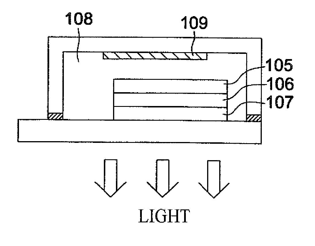
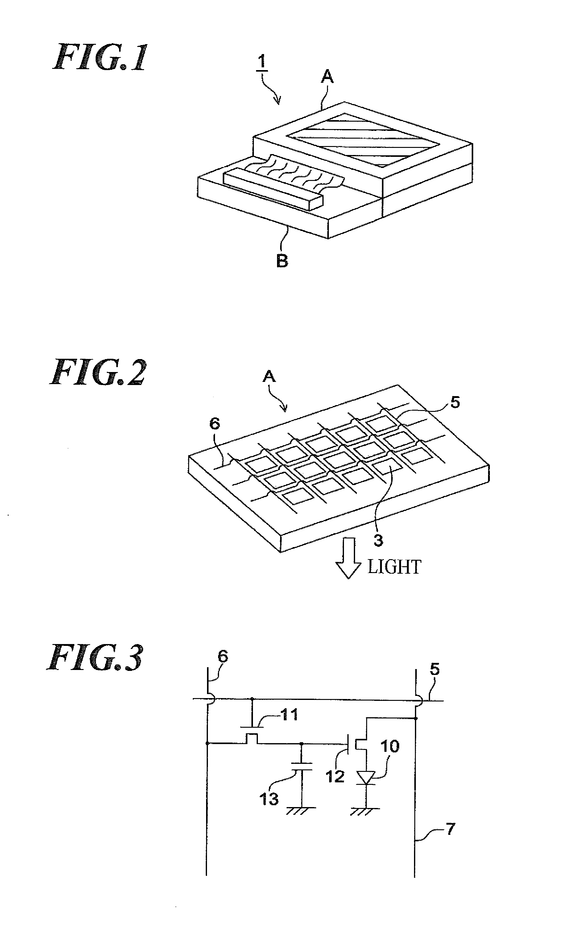
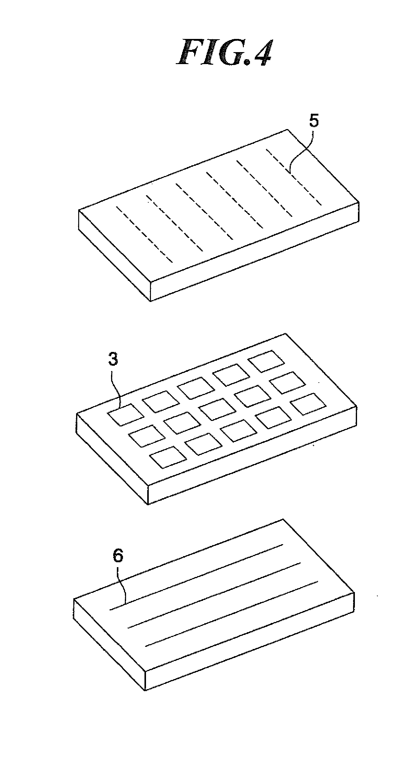
[0342]The thus-obtained organic EL devices 2-1 to 2-12 were evaluated after being respectively sealed and incorporated into a lighting apparatus illustrated in FIG. 5 and FIG. 6, similarly to the organic EL devices 1-1 to 1-15 in Example 1.

[0343]Next, evaluations below were conducted.

[0344](2.1) External Extraction Quantum Efficiency (Also Simply Referred to as “Efficiency”)

[0345]Evaluation was conducted similarly as described in Example 1. The external extraction quantum efficiency was expressed by relative values assuming that of the organic EL device 2-2 (Comparative Example) as 100.

[0346](2.2) Dark Spot

[0347]Each organic EL device ...

example 3

(1) Manufacturing of Organic EL Devices

[0353](1.1) Manufacturing of Organic EL Device 3-1

[0354]A 100-nm-thick ITO (indium tin oxide) film formed on a 100 mm×100 mm×1.1 mm glass substrate (NA-45, from AvanStrate Inc.) was patterned to form an anode. The thus-obtained transparent support substrate having the ITO transparent electrode patterned thereon was then subjected to ultrasonic cleaning in isopropanol, dried with dry nitrogen gas, and subjected to UV-ozone cleaning for 5 minutes.

[0355]On the transparent support substrate, a solution of poly(3,4-ethylenedioxythiophene)-polystyrene sulfonate (PEDOT / PSS, CLEVIOS P VP A14083, from H.C. Starck, Inc.) diluted 70% with pure water was spread by spin coating at 3000 rpm for 30 seconds, and then dried at 200° C. for one hour, to thereby form a first hole transport layer of 20 nm thick.

[0356]The transparent support substrate was fixed to a substrate holder of a commercially-available vacuum deposition apparatus. 200 mg of α-NPD was placed ...


PUM


Abstract

An organic electroluminescent device containing:a six-coordinate, ortho-metalated iridium complex represented by the formula (I):wherein V represents a trivalent linking group and is bound to L1 to L3 through covalent bonds;each of L1 to L3 is represented by the formula (II);X5 and Ir form a coordinate bond;X7 and Ir form a covalent bond;each of X1 to X5 represents a group of elements composing a nitrogen-containing heterocycle, selected from carbon atom or nitrogen atom;at least one of X4 and X5 represents a nitrogen atom;each of X6 to X11 represents a group of element composing an aromatic five-membered ring or aromatic six-membered ring, and is selected from carbon atom or nitrogen atom;when X6 to X11 form an aromatic five-membered ring, X11 merely represents a bond; andR1 represents a substituted aryl group having seven or more carbon atoms.

Description

BACKGROUND OF THE INVENTION[0001]1. Field of the Invention[0002]The present invention relates to an organic electroluminescent device, a display apparatus, and a lighting apparatus.[0003]2. Description of Related Art[0004]An organic electroluminescent device (also referred to as an organic EL device, hereinafter) is a device having a luminescent layer which contains a light-emitting compound held between a cathode and an anode. The organic EL device emits light by injecting electrons and holes into the luminescent layer, allowing them to recombine therein so as to produce excitons which cause emission of light (fluorescence or phosphorescence) upon annihilation. The device attracts public attention to a flat display apparatus or a lighting apparatus of the next generation, by virtue of its capability of luminescence under applied voltage of only several volts to several tens of volts.[0005]Since an organic EL device making use of phosphorescence from excited triplet state, where the...

Claims


Application Information

Patent Timeline
Patent Type & Authority Applications(United States)
IPC IPC(8): H01L51/54
CPCC09K11/06C09K2211/1007C09K2211/1029C09K2211/1044C09K2211/1059H01L51/5036C09K2211/185H01L51/0071H01L51/0085H01L51/5016C09K2211/1092H10K85/657H10K85/342H10K50/11H10K2101/10H10K50/125
Inventor YASUKAWA, NORIKOIKEMIZU, DAIOSHIYAMA, TOMOHIRONISHIZEKI, MASATOTANAKA, TATSUO
Owner UDC IRELAND
Why Eureka
Try Eureka