Integrated Circuit Signal Generation Device

a technology of integrated circuits and signal generation devices, which is applied in the direction of logic circuits using specific components, pulse manipulation, pulse techniques, etc., can solve the problems of fixed and unalterable functionality, time-consuming and error-prone use of machine language or c programming tools, and time-consuming devices, so as to reduce the time needed to configure the device, improve the speed and flexibility of device operation, and minimize communication delays

Inactive Publication Date: 2012-01-26
SALHANY WAYNE F
View PDF4 Cites 5 Cited by
  • Summary
  • Abstract
  • Description
  • Claims
  • Application Information

AI Technical Summary

Benefits of technology

[0017]In one embodiment programming is minimized, errors are minimized, setup and initialization is simplified, design time is reduced, material costs are reduced, a single part number can be used in multiple ways in a single design, space is saved, function is easily modified, overall performance is improved and overall power consumption is reduced.SUMMARY DESCRIPTION
[0022]The exemplary embodiment includes a communications interface. A computer or other client, for example a web browser, can communicate with the device. The attached client can read and set the values in the memory locations. The client can also read and set the mode. Additionally, the mode can be set by logic within the device itself. Another name for mode is state. The mode or state may change from mode to mode frequently or infrequently. It will be seen that communications delays can be minimized in this arrangement. Calculations are executed in the hardware to improve speed and flexibility of operation of the device.
[0023]It will be seen that several advantages of one or more aspects are to provide a configurable device that reduces the time needed to configure the device, reduces the risk of error and improves ease of use. In one or more aspects a higher level of flexibility, configurability, performance and adaptability offers the possibility of larger production runs, lower cost and smaller size for corresponding complexity, improved performance, increased usability and lower power consumption. These and other advantages of one or more aspects will become apparent from a consideration of the ensuing descriptions and accompanying drawings.

Problems solved by technology

Microcontrollers are programmed using machine language or C. Using these programming tools is time consuming and error prone.
These have fixed and unalterable functionality.
These devices is also time consuming and difficult to use.
These devices typically comprise custom products and have the disadvantage of low volume runs and associated high relative cost.
Using these integrated circuit devices is time consuming and space consuming if the desired functionality is complex
These chips are complex.
They are overly expensive and consume too much power for many applications.

Method used


Image

  • Integrated Circuit Signal Generation Device
  • Integrated Circuit Signal Generation Device
  • Integrated Circuit Signal Generation Device

Examples


second embodiment

DESCRIPTION OF A SECOND EMBODIMENT

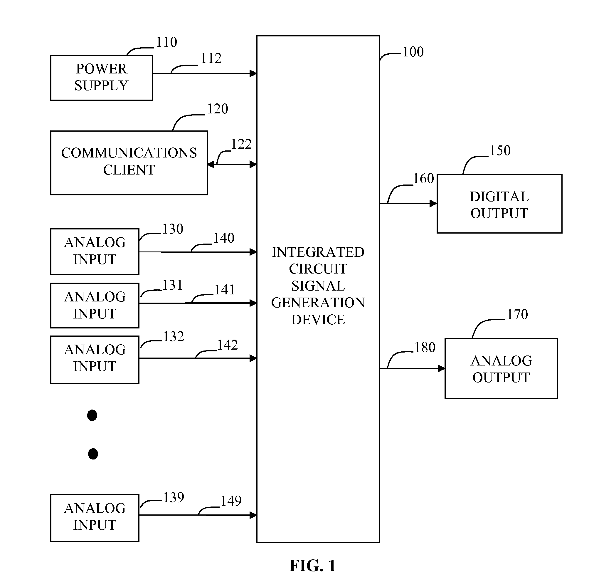
[0076]Consider FIG. 1. In a second embodiment, the device 100 is a microcontroller. In this embodiment there is a digital output 150 connected to the device 100 via electrical connections 160. In this embodiment analog output 170 and electrical connections 180 are omitted.

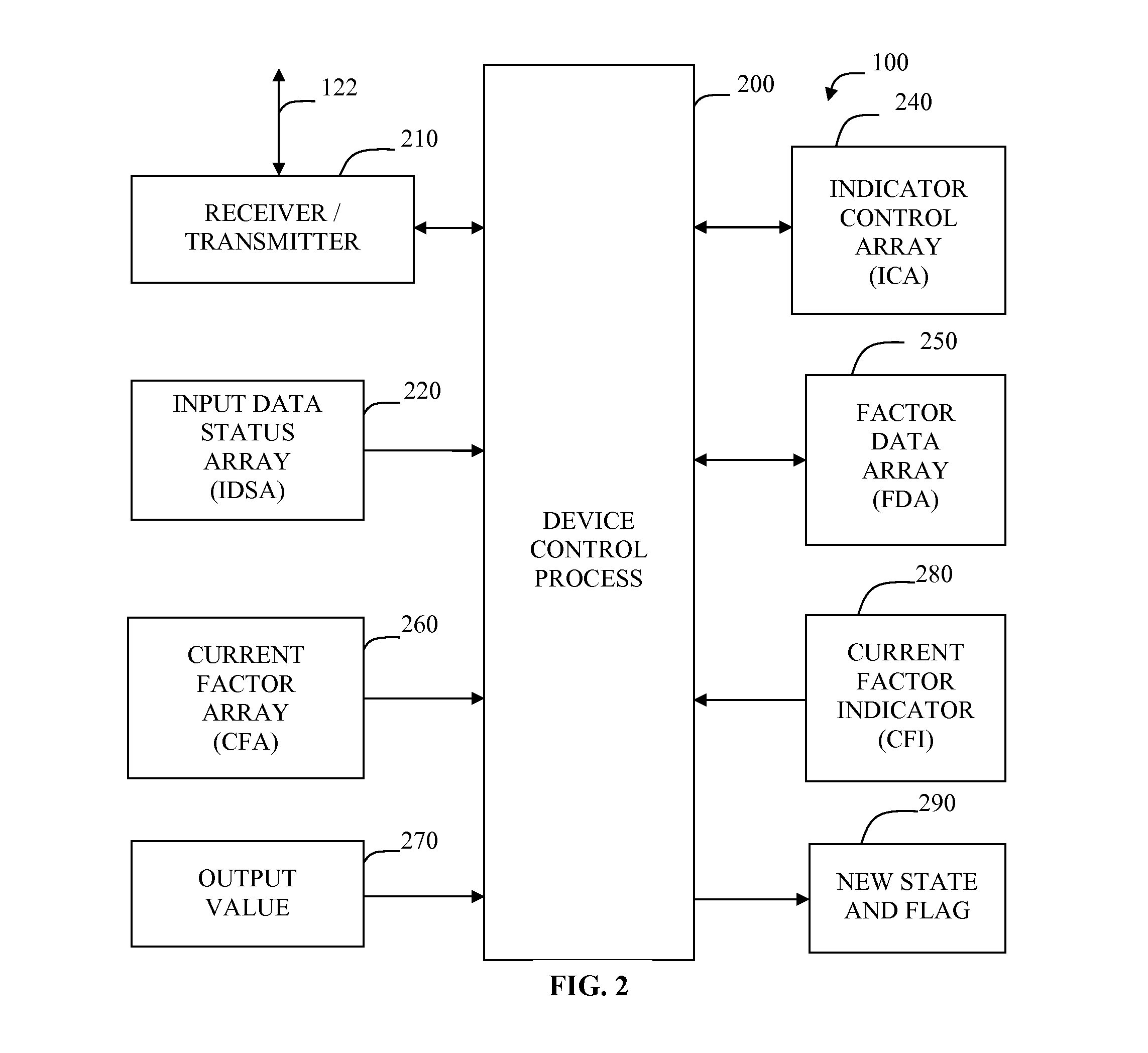
[0077]Consider FIG. 2. In this embodiment the communications client 120 (FIG. 1) is a serial communications terminal, such as HYPERTERM, that communicates with the microcontroller via RS232. The receiver / transmitter 210 includes conventional software for such communications.

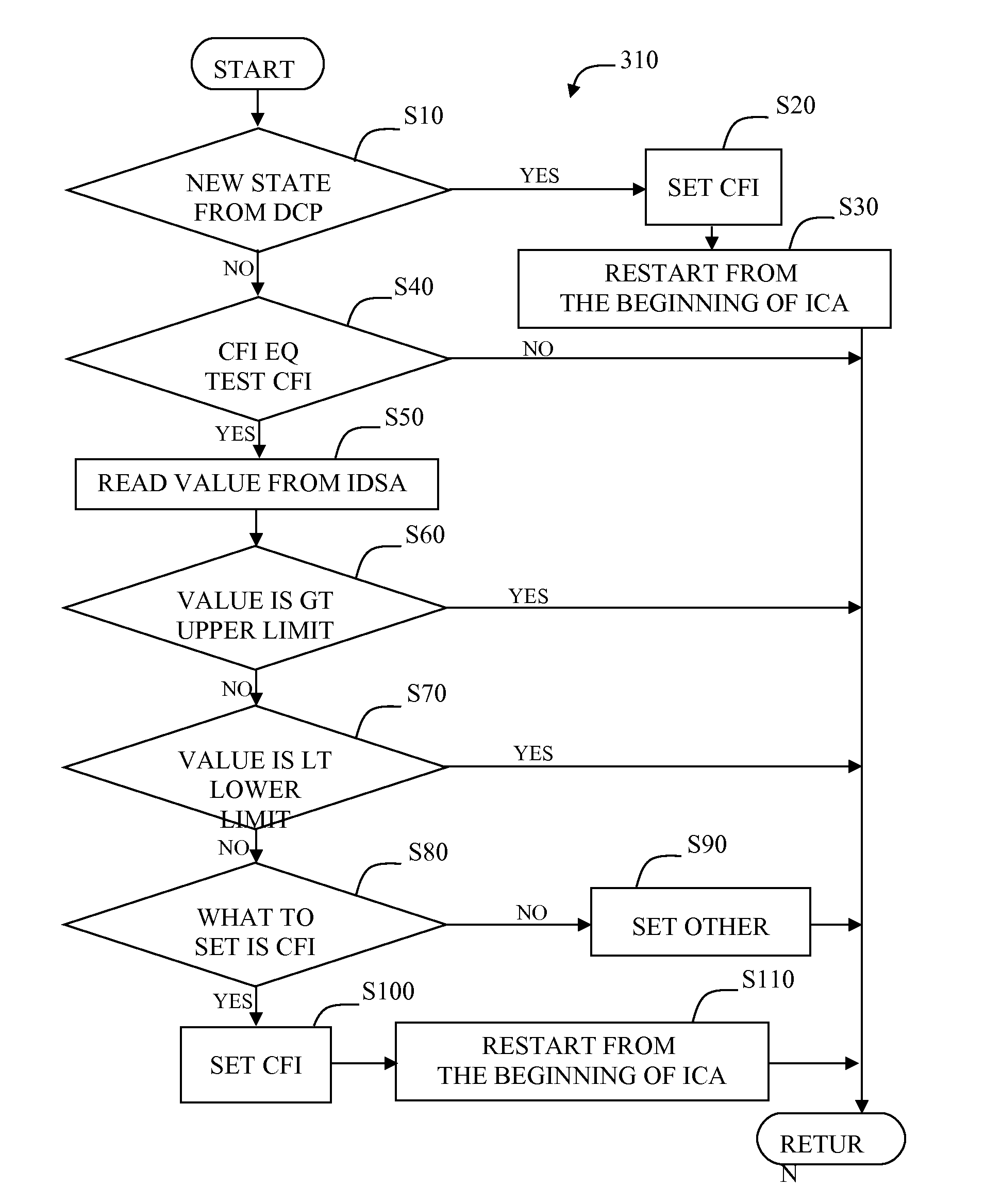
[0078]Consider FIG. 3. In this second embodiment, the device 100 is a general purpose microcontroller. In this embodiment the processes of this fig are implemented in software.

[0079]Consider FIG. 12. In this embodiment the digital output signal is a pulse-width modulated (PWM) digital output signal at a predetermined refresh rate.

[0080]It may be observed that the performance characteristics of the second embodim...

third embodiment

DESCRIPTION OF A THIRD EMBODIMENT

[0082]Consider FIG. 1. In a third embodiment, the device 100 is a field-programmable gate array (FPGA). In this embodiment there is an analog output 170 connected to the device 100 via electrical connections 180. In this embodiment digital output 150 and electrical connections 160 are omitted.

[0083]Consider FIG. 2. In this embodiment the communications client 120 (FIG. 1) is a custom program with a graphic user interface that communicates with the FPGA using the universal serial bus (USB). The receiver / transmitter 210 includes conventional circuitry for such communications.

[0084]It may be observed that the performance characteristics of the third embodiment will differ from those of the first two embodiments. It may further be observed that this embodiment could potentially be paired with a linear amplifier to produce a well controlled light control system.


PUM


Abstract

An electronic integrated-circuit device is described in which mode control commands are stored. Mode parameters are also stored in the device. One or more inputs are used according to a predetermined process as determined by the stored parameters according to the stored commands and current mode. One or more output signals are produced. In various applications an output signal may be input to a sound amplifier, a lamp, a motor, a servo, etc. One application is a variety of sensor fusion. Procedural programming is avoided. The device operates with more speed and flexibility than other available configurations. Higher level supervisory management and control is useful for setup and initialization and is optional during operation. Selected platforms include microcontrollers; field programmable gate arrays (FPGAs) and application specific integrated circuits (ASICs).

Description

CROSS-REFERENCE TO RELATED APPLICATION[0001]NoneFEDERALLY SPONSORED RESEARCH[0002]Not ApplicableSEQUENCE LISTING OR PROGRAM[0003]Not ApplicableBACKGROUND FIELD[0004]This application relates to electrical devices and circuits that have an output proportional to the value of a mathematical expression, specifically a polynomial mathematical expression.BACKGROUND PRIOR ART[0005]Programmable logic controllers (PLC) are typically programmed using ladder logic. Microcontrollers are programmed using machine language or C. Using these programming tools is time consuming and error prone.[0006]Memory devices store data and logic devices perform specific logic. These have fixed and unalterable functionality. They are not programmable. Programmable logic devices (PLDs), including field programmable gate arrays (FPGAs) mix functionality with programmability. These devices is also time consuming and difficult to use.[0007]In the attempt to reduce errors and increase productivity, blocks of logic h...

Claims


Application Information

Patent Timeline
Patent Type & Authority Applications(United States)
IPC IPC(8): H03K5/01
CPCG06F1/02
Inventor SALHANY, WAYNE F.
Owner SALHANY WAYNE F
Why Eureka
Try Eureka