Vibration generating apparatus

a generation apparatus and vibration technology, applied in the direction of mechanical vibration separation, dynamo-electric converter control, dynamo-electric machines, etc., can solve the problems of poor damping sharpness, long damping period, and inability to guarantee a complete 180 degree shift, etc., to achieve low cost and high yield

Inactive Publication Date: 2012-02-02
SANYO SEIMITSU
View PDF11 Cites 43 Cited by
  • Summary
  • Abstract
  • Description
  • Claims
  • Application Information

AI Technical Summary

Benefits of technology

[0020]Summarizing the advantageous effects of the present invention, it is possible to design a vibration generating apparatus which utilizes a beat vibration, so it is possible to provide a vibration generating apparatus which is high in yield, low in cost, and able to exhibit a vibration tactile haptic effects even if there are variations in the natural frequency of the mechanical vibrator.

Problems solved by technology

The above resonance actuator is made to operate in a resonance mode using a forced vibration frequency the same as its natural frequency (resonant frequency), so while instantaneous excitation is easy in the excitation process which rapidly increases the acceleration, in the damping process for damping the once high acceleration resonance actuator, since the resonance actuator will have quite of a bit of variation in natural frequency for each specimen, even if the phase of the damping use actuator signal completely shifts by 180 degrees from the excitation use actuator signal, in reality there is no guarantee of a complete 180 degree shift with respect to the phase of the vibration and displacement of the resonance actuator.
Due to this advanced phase difference or retarded phase difference which occurs unavoidably due to variations in the natural frequency, depending on the timing of the end of application of the damping use actuator signal, incomplete stopping of the mechanical vibrator or restart after stopping will be induced, so the free damping period remains longer until entering the insensitive zone and the sharpness of the damping becomes poor.

Method used


Image

  • Vibration generating apparatus
  • Vibration generating apparatus
  • Vibration generating apparatus

Examples


Embodiment Construction

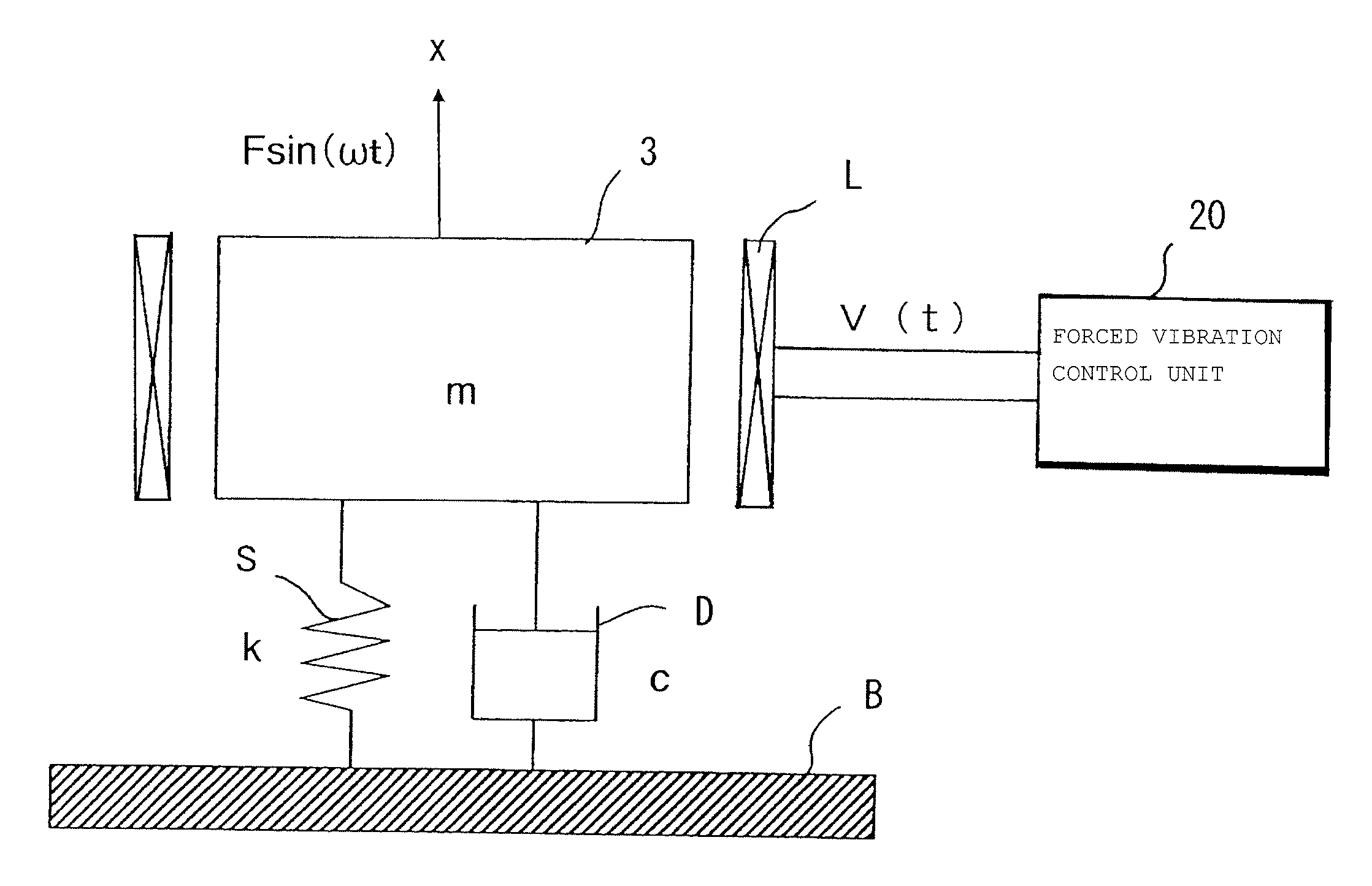
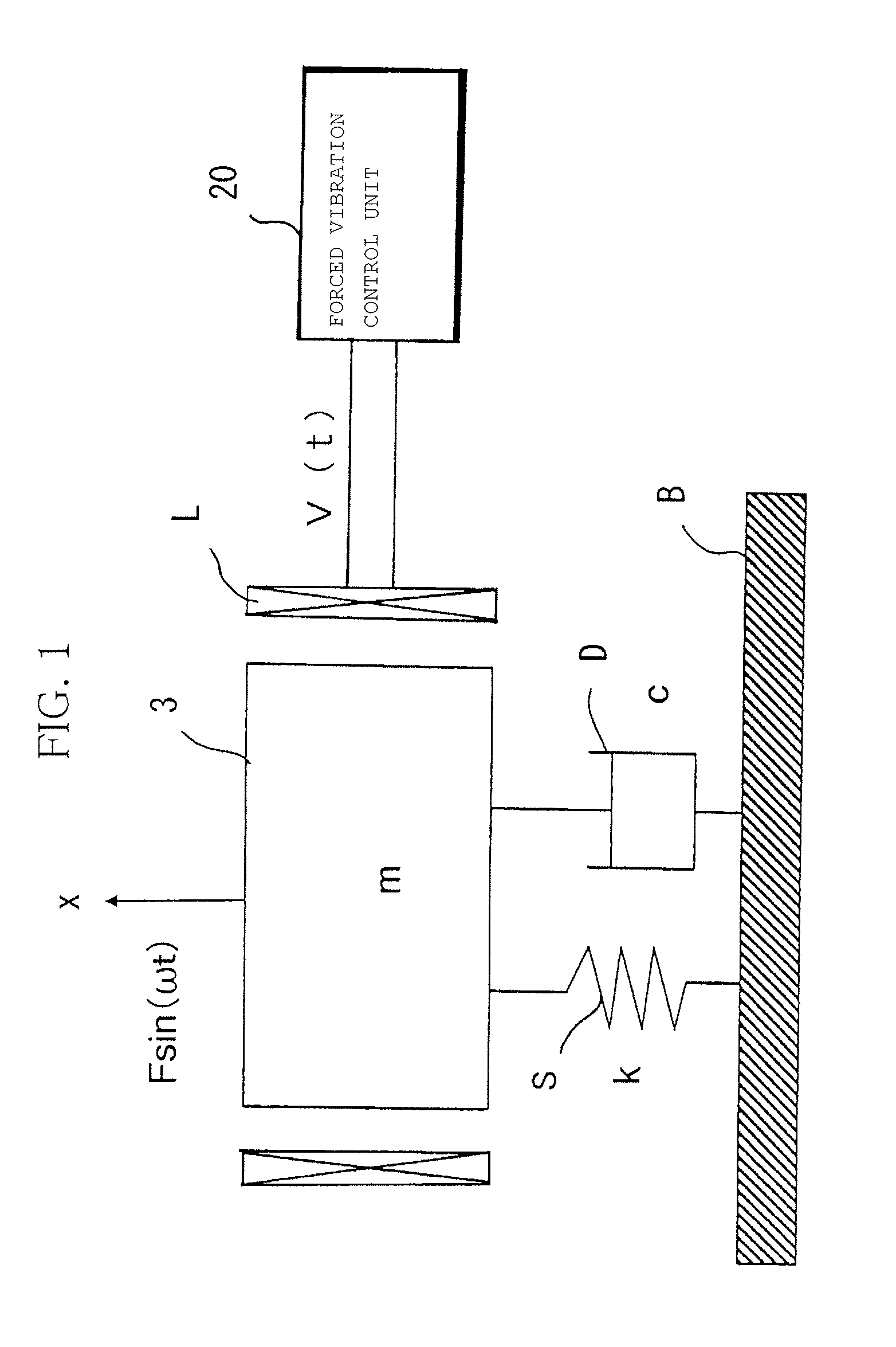
[0068]Next, embodiments of the present invention will be explained based on the attached figures. The vibration generating apparatus of the present embodiment, as conceptually shown in FIG. 1, has a vibration linear actuator of damping system forced vibration which uses a spring element S of a spring constant “k” and a damper D of an attenuation coefficient “c” in parallel to support a mechanical vibrator 3 having a permanent magnet of a mass “m” at a fastening part B. The vibration linear actuator includes an electromagnetic coil L which generates a dynamic magnetic field for giving a sine wave external force F sin (ωt) causing the mechanical vibrator 3 to reciprocatively vibrate in a non-contact manner. The vibration generating apparatus further has a forced vibration controller 20 which generates a drive voltage V(t) of an alternating current which is supplied to the electromagnetic coil L. Here, F is a constant, w is the forced (input) angular frequency, and f=2π / ω is the forced...


PUM


Abstract

A vibration generating apparatus with high yield, low cost, and can exhibit vibration tactile haptic effects even with variation in the natural frequency of a mechanical vibrator, including a damping system having a damping ratio ζ<1 to support a mechanical vibrator to a fastening part, and a magnetizing unit generating a dynamic magnetic field to vibrate the mechanical vibrator by non-contact, the mechanical vibrator generating a beat vibration by making the frequency of a drive voltage applied to the magnetizing unit, from a drive start or middle of drive, to be a non-resonant frequency out of a damped natural frequency of the mechanical vibrator, wherein the apparatus comprises a forced vibration control unit controlling to stop application of the drive voltage, in a beat wave defining an amplitude of the beat vibration, at a second valley part after a first peak part from the side of the drive start.

Description

CROSS-REFERENCE TO RELATED APPLICATION[0001]This application is based upon and claims the benefit of priority of the prior Japanese Patent Application No. 2010-167714 filed on Jul. 27, 2010, the prior Japanese Patent Application No. 2010-255579 filed on Nov. 16, 2010 and the prior Japanese Patent Application No. 2011-150975 filed on Jul. 7, 2011, the entire contents of which are incorporated herein by reference.BACKGROUND OF THE INVENTION[0002]1. Field of the Invention[0003]The present invention relates to a vibration generating apparatus which can be built into a mobile phone, touch panel, or other device, more particularly relates to a vibration generating apparatus which exhibits a vibration tactile haptic effects of instantaneous vibration.[0004]2. Description of the Related Art[0005]A vibration generating apparatus giving the vibration tactile haptic effects disclosed in Japanese Patent Publication (A) No. 2008-521597 employs a resonant forced vibration system. A signal generat...

Claims


Application Information

Patent Timeline
Patent Type & Authority Applications(United States)
IPC IPC(8): H02P25/02H02K33/00B06B1/04H02P25/06
CPCB06B1/0207B06B1/045H02K33/16B06B2201/70B06B2201/30H02P25/032H02K33/00
Inventor MASAHIKO, MIYAZAKI
Owner SANYO SEIMITSU
Why Eureka
Try Eureka