Power amplifier

a power amplifier and amplifier technology, applied in amplifiers, amplifiers with semiconductor devices/discharge tubes, amplifiers, etc., can solve the problems of affecting the performance of power amplifiers, and difficulty in coupling power amplifiers with adjustment circuit blocks

Active Publication Date: 2012-02-02
SAMSUNG ELECTRO MECHANICS CO LTD +1
View PDF5 Cites 69 Cited by
  • Summary
  • Abstract
  • Description
  • Claims
  • Application Information

AI Technical Summary

Benefits of technology

[0012]An aspect of the present invention provides a power amplifier capable of supplying variable bias to an amplifier circuit by accurately transferring the envelope components of an input signal during the supply of active bias power to the amplifier circuit.

Problems solved by technology

However, in the above-mentioned InGaP / GaAs HBT process, manufacturing costs are increased and the power amplifier is formed in a multi-chip structure and thus, it is difficult to couple the power amplifier with an adjustment circuit block implemented by the CMOS process in order to improve linearity, as compared with the CMOS process.
Comparing with the HBT process, the CMOS process slightly degrades the performance of the power amplifier.

Method used


Image

  • Power amplifier
  • Power amplifier
  • Power amplifier

Examples


Embodiment Construction

[0030]Hereinafter, exemplary embodiments of the present invention will now be described in detail with reference to the accompanying drawings.

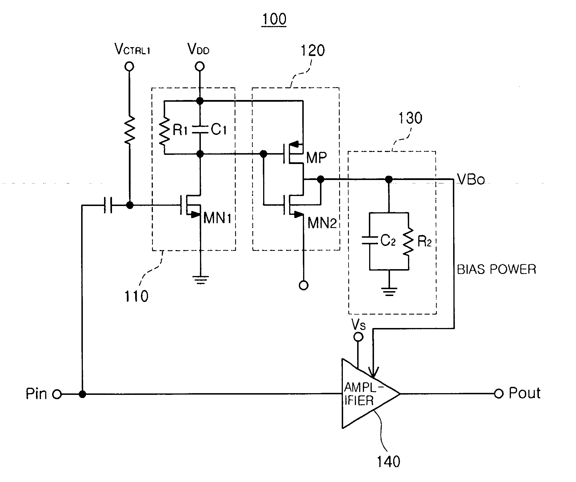
[0031]FIG. 3 is a schematic configuration diagram of an exemplary embodiment of a power amplifier according to the present invention.

[0032]Referring to FIG. 3, a power amplifier 100 according to the present invention may include an envelope detector 110, a bias power generator 120, and amplifier 140, and a low band pass filter unit 130.

[0033]The envelope detector 110 may include a first resistor R1, a first capacitor C1, and a first N-type MOSFET MN1.

[0034]The first resistor R1 and the first capacitor C1 are connected to each other in parallel. One terminal of the first resistor R1 and one terminal of the first capacitor C1 are connected to a driving power terminal supplying driving power VDD having a preset voltage level and another terminal formed at the opposite side to one terminal of the first resistor R1 and another terminal formed at th...


PUM


Abstract

There is provided a power amplifier capable of supplying variable bias to an amplifier circuit by accurately transferring the envelope components of an input signal during the supply of active bias power to the amplifier circuit. The power amplifier includes: an envelope detector detecting an envelope of an input signal; a bias power generator including at least one P-type MOSFET and one N-type MOSFET connected to each other in an inverter manner between a driving power terminal supplying driving power having a preset voltage level and a reference bias power terminal supplying preset reference bias power to generate bias power varied according to detection results from the envelope detector; and an amplifier amplifying the input signal according to the bias power level from the bias power generator.

Description

CROSS-REFERENCE TO RELATED APPLICATIONS[0001]This application claims the priority of Korean Patent Application No. 10-2010-0072730 filed on Jul. 28, 2010, in the Korean Intellectual Property Office, the disclosure of which is incorporated herein by reference.BACKGROUND OF THE INVENTION[0002]1. Field of the Invention[0003]The present invention relates to a power amplifier, and more particularly, to a power amplifier capable of supplying variable bias to an amplifier circuit by accurately transferring the envelope components of an input signal during the supply of active bias power to the amplifier circuit.[0004]2. Description of the Related Art[0005]Recently, blocks configuring a wireless transceiver are being integrated into a single chip by using a complementary metal oxide semiconductor (CMOS) process technology. In this process, only the power amplifier, among the blocks of the wireless transceiver, is implemented by an indium gallium phosphide (InGaP) / gallium arsenide (GaAs) Het...

Claims


Application Information

Patent Timeline
Patent Type & Authority Applications(United States)
IPC IPC(8): H03G3/20
CPCH03F1/0266H03F2200/555H03F2200/105H03F3/195
Inventor KOO, BON HOONSON, KI YONGHONG, SONG CHEOLKIM, GYU SUCKNA, YOO SAM
Owner SAMSUNG ELECTRO MECHANICS CO LTD
Why Eureka
Try Eureka