Differential amplifier circuit

a technology of amplifier circuit and amplifier circuit, which is applied in the direction of differential amplifiers, amplifiers with semiconductor devices/discharge tubes, dc-amplifiers with dc-coupled stages, etc., can solve the problems of hindering cost reduction and size reduction of the regulator circuit, and difficulty in forming capacitors, so as to reduce cost and reduce capacitance. small, the effect of small capacitan

Active Publication Date: 2012-02-02
LAPIS SEMICON CO LTD
View PDF4 Cites 10 Cited by
  • Summary
  • Abstract
  • Description
  • Claims
  • Application Information

AI Technical Summary

Benefits of technology

[0008]In the regulator circuit disclosed in Japanese Patent No. 4054804 (WO 2003 / 091817), a capacitor in the cancel signal generating circuit has a very small capacitance ranging from 0.001 pF to 0.1 pF. It is difficult to form a capacitor of a very small capacitance in such a range by controlling a distance between two polar plates of the capacitor, as unevenness may be inevitably included in the distance between these two polar plates. In order to ensure a very small capacitance in the above-mentioned range, trimming may be performed by adding a trimming circuit and a capacitor dedicated to the trimming. However, this hinders cost reduction and size reduction of the regulator circuit.

Problems solved by technology

It is difficult to form a capacitor of a very small capacitance in such a range by controlling a distance between two polar plates of the capacitor, as unevenness may be inevitably included in the distance between these two polar plates.
However, this hinders cost reduction and size reduction of the regulator circuit.

Method used


Image

  • Differential amplifier circuit
  • Differential amplifier circuit
  • Differential amplifier circuit

Examples


first embodiment

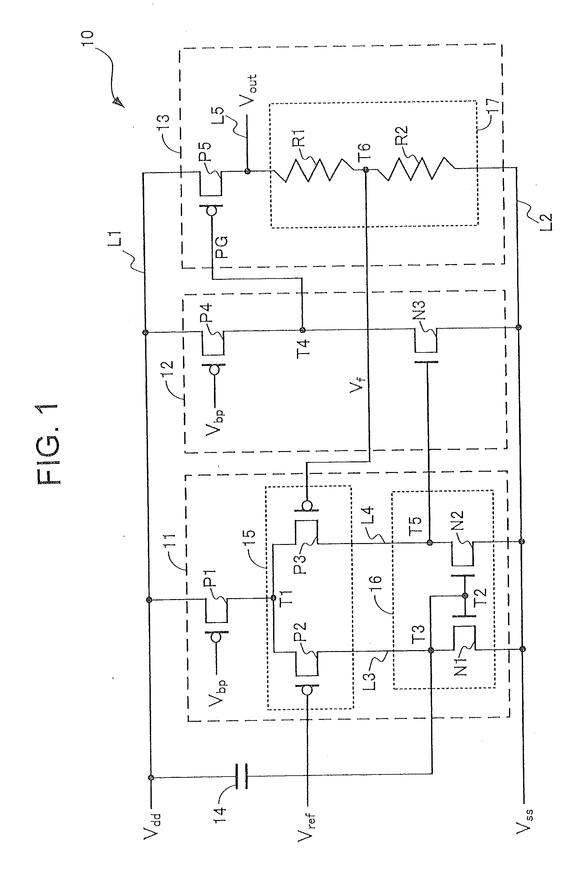
[0026]First, the structure of a stabilizer power supply circuit (series regulator) 10 according to a first embodiment of the present invention will be described with reference to FIG. 1. FIG. 1 is an equivalent circuit diagram of the stabilizer power supply circuit 10. The stabilizer power supply circuit 10 is an example of a differential amplifier circuit.

[0027]As shown in FIG. 1, a stabilizer power supply circuit 10 includes a power supply line L1 to which a power supply voltage Vdd is supplied from a direct-current power supply (i.e., power supply voltage source), a ground line L2 connected to a ground potential Vss, an input part 11, an amplifying part 12, an output part 13, and a capacitor 14 (i.e., noise permitting part). The input part 11, the amplifying part 12, and the output part 13 are disposed between the power supply line L1 and the ground line L2. The capacitor 14 is disposed between the power supply line L1 and the input part 11.

[0028]The input part 11 includes a tran...

second embodiment

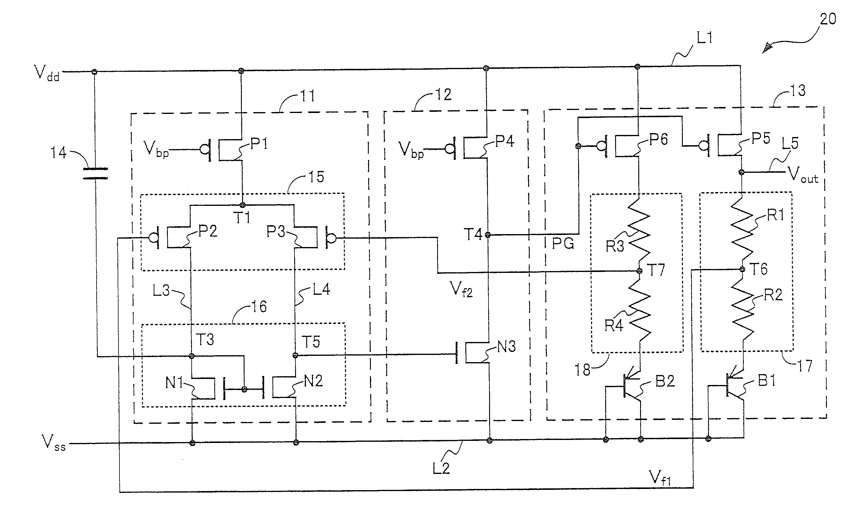
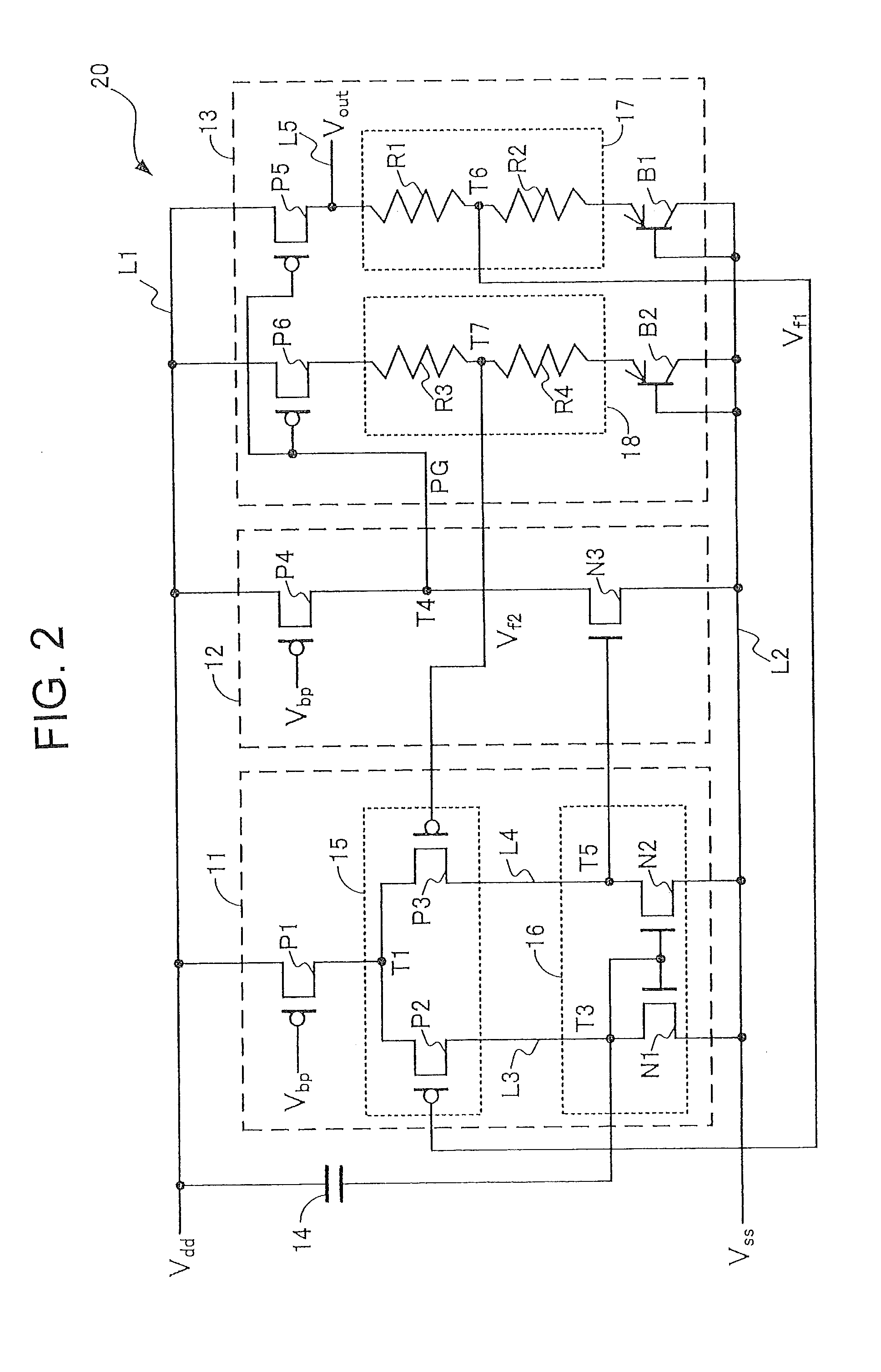
[0044]The structure of a reference voltage supply circuit (band-gap reference circuit) 20 according to a second embodiment of the present invention is described by referring to FIG. 2. FIG. 2 is an equivalent circuit diagram of the reference voltage supply circuit 20. Similar reference numerals and symbols are used to designate similar elements and actions in the first and second embodiments. The reference voltage supply circuit 20 is an example of a differential amplifier circuit.

[0045]Like the power supply circuit 10 of the first embodiment, the reference voltage supply circuit 20 includes a power supply line L1 to which a power supply voltage Vdd is supplied from a direct-current power supply, a ground line L2 connected to a ground potential Vss, an input part 11, an amplifying part 12, an output part 13, and a capacitor 14 functioning as a noise permitting part. In the following description, parts and elements different from those of the power supply circuit 10 of the first embo...

third embodiment

[0052]The structure of a differential amplifier circuit 30 according to a third embodiment of the present invention will be described with reference to FIG. 3. FIG. 3 is an equivalent circuit diagram of the differential amplifier circuit 30. Similar reference numerals and symbols are used to designate similar elements and actions in the first, second and third embodiments. An operational amplifier is used as an example of the differential amplifier circuit 30.

[0053]Like the power supply circuit 10 of the first embodiment, the operational amplifier (or differential amplifier circuit) 30 includes a power supply line L1 to which a power supply voltage Vdd is supplied from a direct-current power supply, a ground line L2 connected to a ground potential Vss, an input part 11, an amplifying part 12, an output part 13, and a capacitor 14 functioning as a noise permitting part. In the following description, parts different from those of the stabilizer power supply circuit 10 of the first emb...


PUM


Abstract

A differential amplifier circuit can reduce consumption current and the circuit size while improving a power supply rejection ratio. The differential amplifier circuit includes a power supply line and an input part that includes an input circuit and an active load. The input circuit includes two differential input elements, and the active load includes two transistors connected to the two differential input elements. The input part generates a differential signal in response to an input signal given to the two differential input elements. The differential amplifier circuit also includes an amplifying part for generating an output voltage generating signal by amplifying the differential signal. The differential amplifier circuit also includes an output part for generating an output voltage based on the output voltage generating signal and a power supply voltage. The differential amplifier circuit includes a noise permitting part located between control terminals of the two transistors and the power supply line.

Description

BACKGROUND OF THE INVENTION[0001]1. Field of the Invention[0002]The present invention relates to a differential amplifier circuit for supplying a certain voltage, and in particular, to a technique of improving a power supply rejection ratio of the differential amplifier circuit.[0003]2. Description of Related Art[0004]Known differential amplifier circuits include a so-called regulator circuit designed to compare a certain voltage derived from a power supply voltage with a reference voltage, and supply a desired constant voltage (output voltage) in accordance with a result of the comparison. Such a regulator circuit is disclosed, for example, in Japanese Patent Application Publication (Kokai) No. 2003-177829 and Japanese Patent No. 4054804 (or WO 2003 / 091817). In this regulator circuit, the reference voltage is supplied to the gate of one of paired differential input elements in an input circuit, and the certain voltage derived from the power supply voltage is supplied to the gate of...

Claims


Application Information

Patent Timeline
Patent Type & Authority Applications(United States)
IPC IPC(8): H03F3/45
CPCH03F3/45183H03F3/45475H03F2203/45674H03F2203/45528H03F3/45632
Inventor OOMORI, TETSUO
Owner LAPIS SEMICON CO LTD
Why Eureka
Try Eureka