
RF isolation switch circuit

a technology of isolation switch and switch circuit, which is applied in the direction of electronic switching, waveguide type devices, pulse techniques, etc., can solve problems such as degrading circuit linearity, and achieve the effect of reducing the threshold voltage of the main transistor and reducing the source-to-drain resistan

Active Publication Date: 2012-02-02
QUALCOMM INC
View PDF13 Cites 18 Cited by
  • Summary
  • Abstract
  • Description
  • Claims
  • Application Information

AI Technical Summary

Benefits of technology

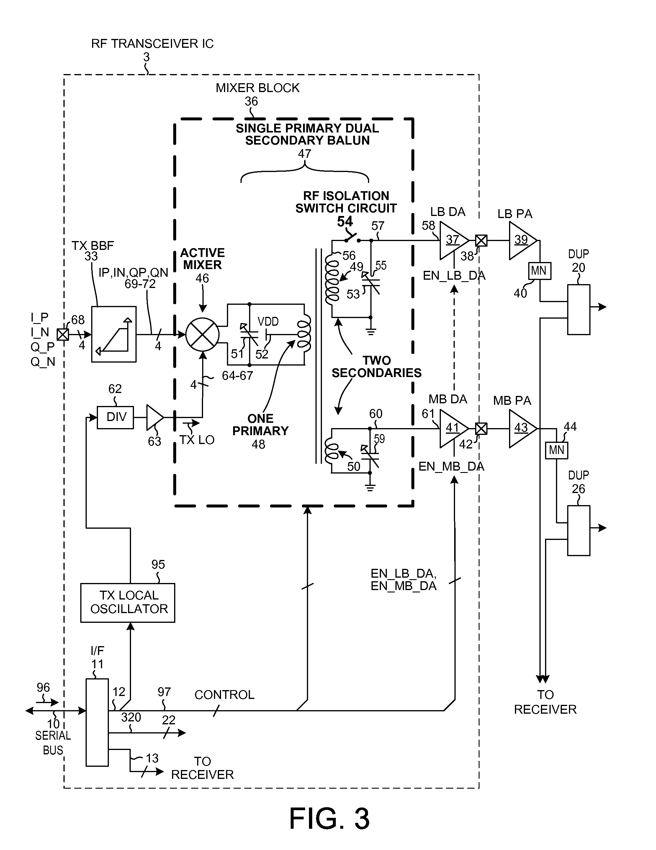
[0010]In addition, a resistor resistively couples the drain of the main transistor to the second control input conductor so that when the RF isolation switch circuit is to be turned off, the drain of the main transistor is resistively pulled up to the digital logic high voltage (for example, 1.3 volts) present on the second control input conductor. This helps assure that the gate voltage of the main transistor does not rise above the drain voltage and helps prevent the main transistor from leaking.
[0012]In a second aspect, an RF isolation switch circuit includes a main transistor having a separately controllable bulk electrode or terminal. In a first mode of operation, the RF isolation switch circuit is to be turned on. A first switch transistor disposed between the bulk terminal and the source terminal of the main transistor is turned on to short the bulk of the main transistor to the source of the main transistor. A second switch transistor usable to couple the bulk through a resistor to a ground conductor is turned off. Shorting the bulk to the source when the RF switch is on reduces the threshold voltage of the main transistor, thereby helping keep the main transistor turned on and helping reduce the source-to-drain on resistance through the main transistor.

Problems solved by technology

Although these conventional RF switch circuits operate satisfactorily well in many instances, the RF switches do introduce unwanted parasitic capacitances and do degrade circuit linearity.

Method used


Image

  • RF isolation switch circuit
  • RF isolation switch circuit
  • RF isolation switch circuit

Examples


Embodiment Construction

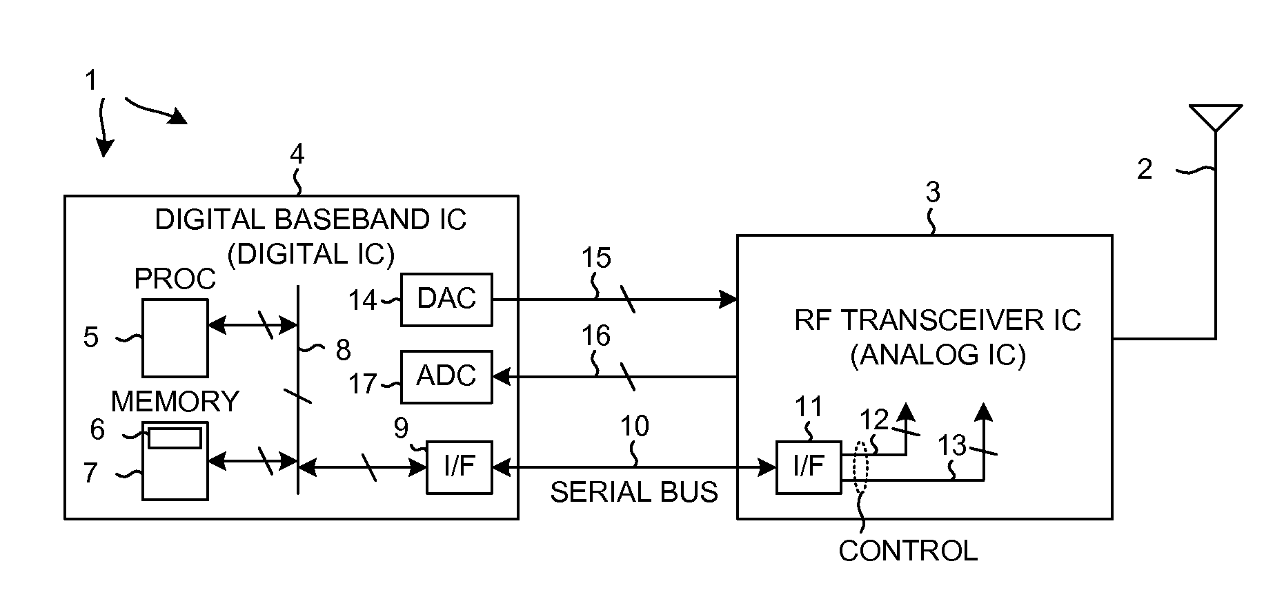
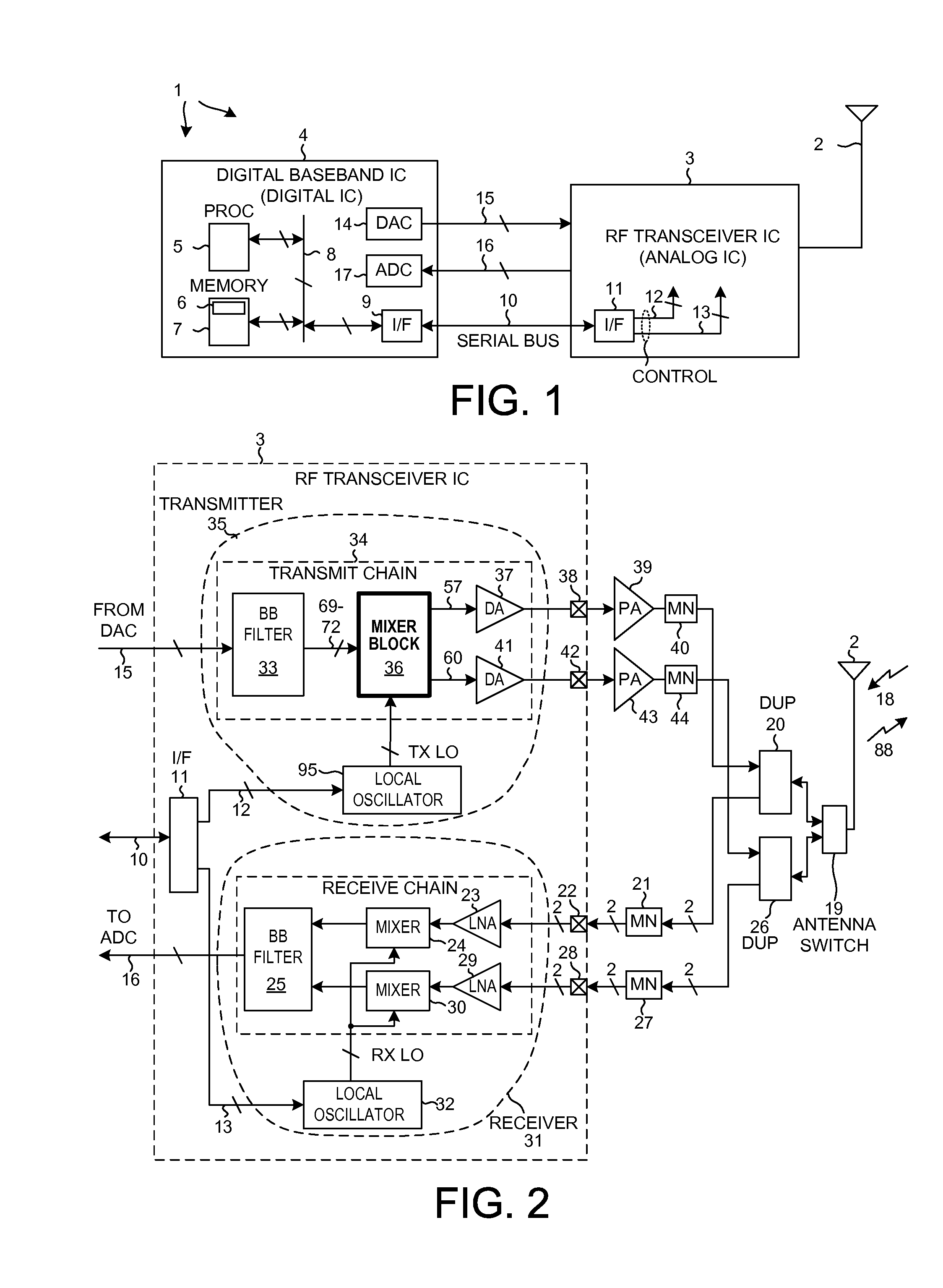
[0034]FIG. 1 is a diagram of a mobile communication device 1 that includes an RF isolation switch circuit in accordance with a first aspect. In this example, mobile communication device 1 is a multi-band cellular telephone handset. Device 1 includes (among other parts not illustrated) an antenna 2 usable for receiving and transmitting cellular telephone communications, an RF (Radio Frequency) transceiver integrated circuit 3, and a digital baseband processor integrated circuit 4. In some examples, the transceiver circuitry and the digital baseband circuitry are implemented on the same integrated circuit, but a two integrated circuit implementation is set forth here for illustration purposes.

[0035]Digital baseband integrated circuit 4 includes a processor 5 that executes a program 6 of processor-executable instructions. Program 6 is stored in a processor-readable medium 7 that in this case is a semiconductor memory. Processor 5 accesses memory 7 via local bus 8. Processor 5 interacts...


PUM


Abstract

In a first aspect, an RF switch includes a main transistor and a gate-to-source shorting circuit. When the RF switch is turned off, the gate-to-source shorting circuit is turned on to short the source and gate of the main transistor together, thereby preventing a Vgs from developing that would cause the main transistor to leak. When the RF switch is turned on, the gate-to-source shorting circuit is turned off to decouple the source from the gate. The gate is supplied with a digital logic high voltage to turn on the main transistor. In a second aspect, an RF switch includes a main transistor that has a bulk terminal. When the RF switch is turned off, the bulk is connected to ground through a high resistance. When the RF switch is turned on, the source and bulk are shorted together thereby reducing the threshold voltage of the main transistor.

Description

CROSS-REFERENCE TO RELATED APPLICATION[0001]This application claims the benefit under 35 U.S.C. §119 of Provisional Application Ser. No. 61 / 368,579, filed Jul. 28, 2010, entitled “RF Isolation Switch Circuit”, by Yan et al., said provisional application being incorporated herein by reference.BACKGROUND[0002]1. Technical Field[0003]The present disclosure relates to RF isolation switch circuits.[0004]2. Background Information[0005]There are many places in high frequency Radio Frequency (RF) circuits where a source of an RF signal is to be selectably either coupled to a load or is to be isolated from the load. The term “RF switch” is sometimes used to refer to a circuit that can be controlled either to couple the RF source to the load or to disconnect and isolate the RF source from the load. One location where such an RF switch is used is in a radio transmitter in the signal path of an RF signal between the transmitter balun and the transmitter driver amplifier. An RF transmit signal a...

Claims


Application Information

Patent Timeline
IPC IPC(8): H01P1/10H03K17/687H03K17/00H01L21/336
CPCH03K17/063H03K17/161H03K2217/0054H03K2017/066H03K2217/0018H03K17/687H03H11/32H03K17/06H03K17/16H04B1/48
Inventor YAN, HONGYANSANKARANARAYANAN, JANAKIRAM GANESHASURI, BHUSHAN SHANTIKHATRI, HIMANSHUPANIKKATH, VINOD V.
Owner QUALCOMM INC
Learn More