Carbon material conversion process comprising two liquefaction stages in a boiling bed in the presence of hydrogen generated by non-fossil sources

a technology of non-fossil source hydrogen and carbon material, which is applied in the direction of hydrocarbon oil treatment products, sustainable manufacturing/processing, energy input, etc., can solve the problems of general production of greenhouse gas emissions and achieve the effect of limiting greenhouse gas emissions

Inactive Publication Date: 2012-02-16
INST FR DU PETROLE
View PDF2 Cites 24 Cited by
  • Summary
  • Abstract
  • Description
  • Claims
  • Application Information

AI Technical Summary

Benefits of technology

[0013]The issue for the industrial development of the direct liquefaction of carbon material is therefore to limit the greenhouse ga

Problems solved by technology
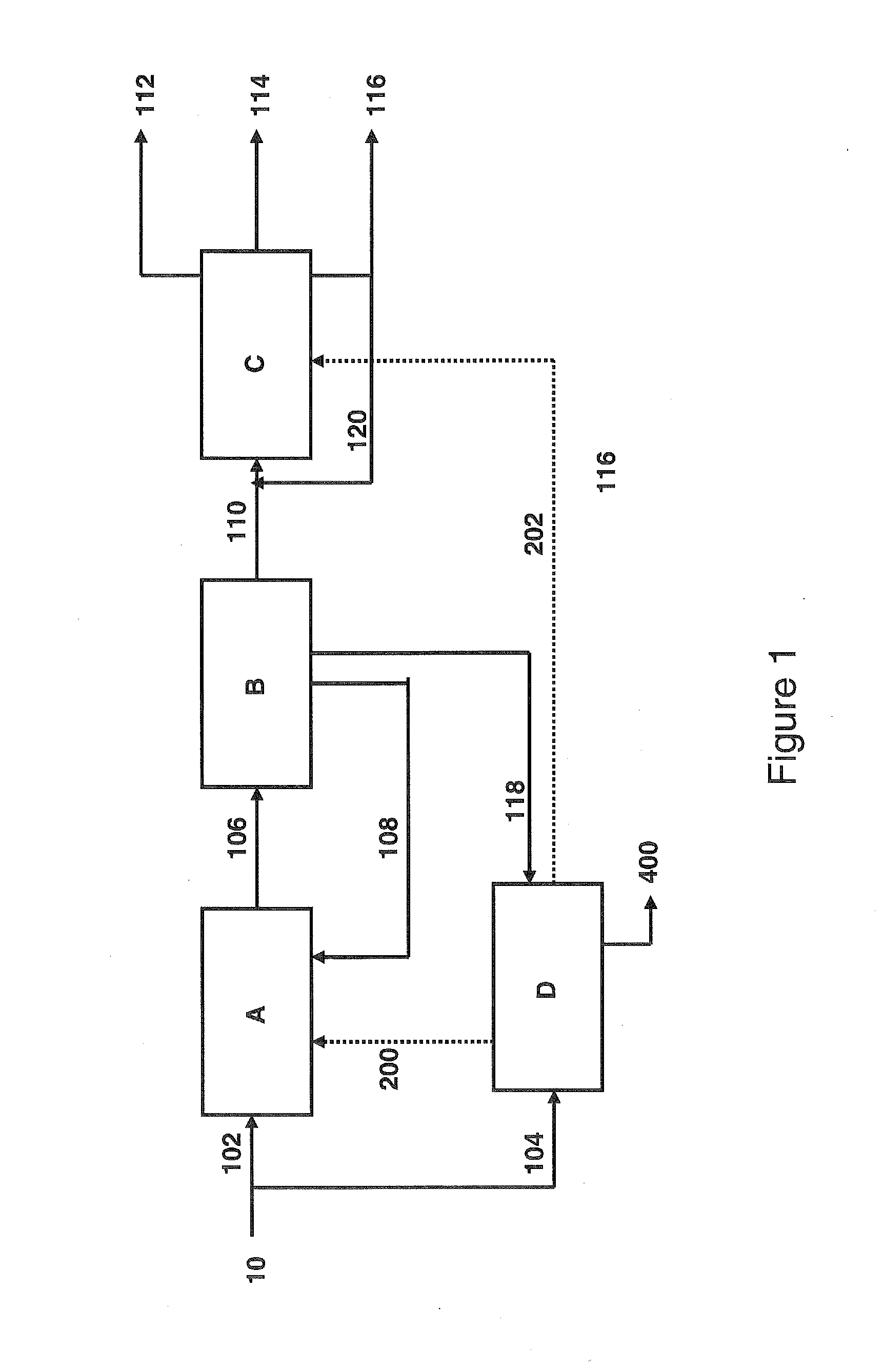
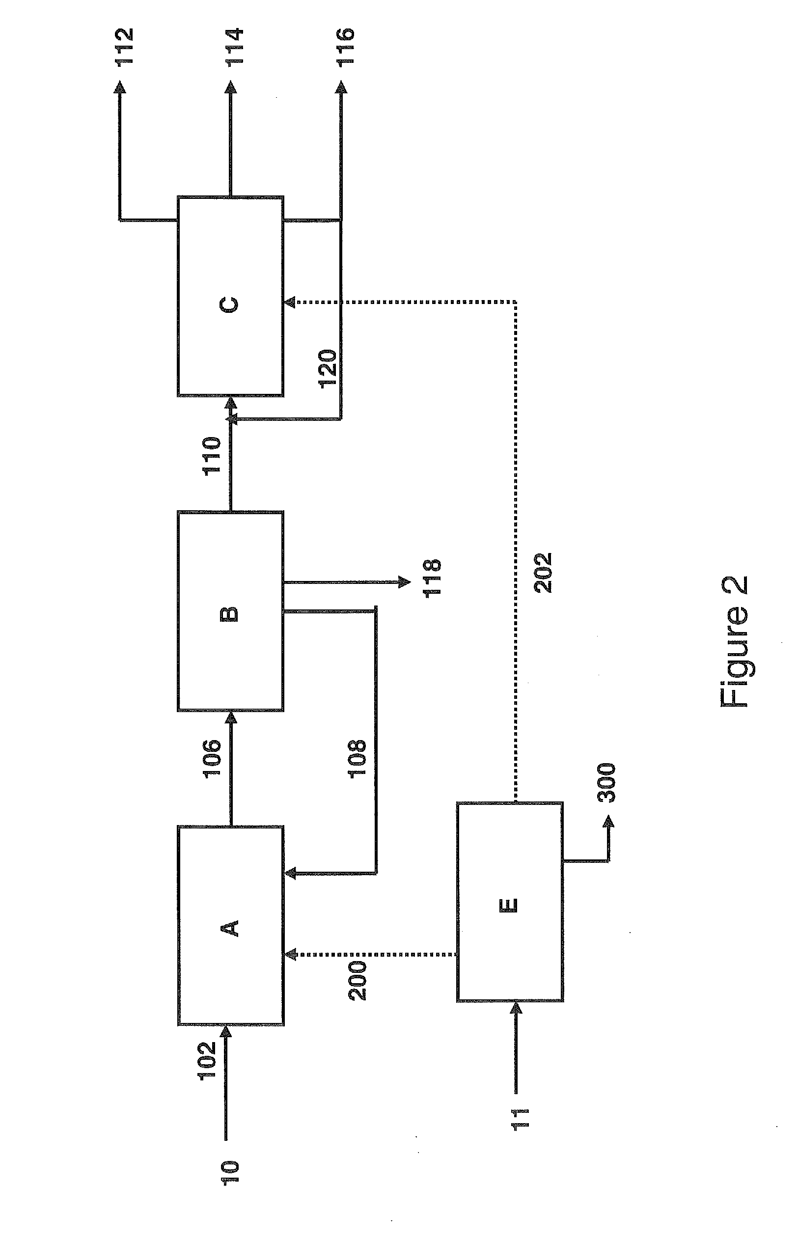
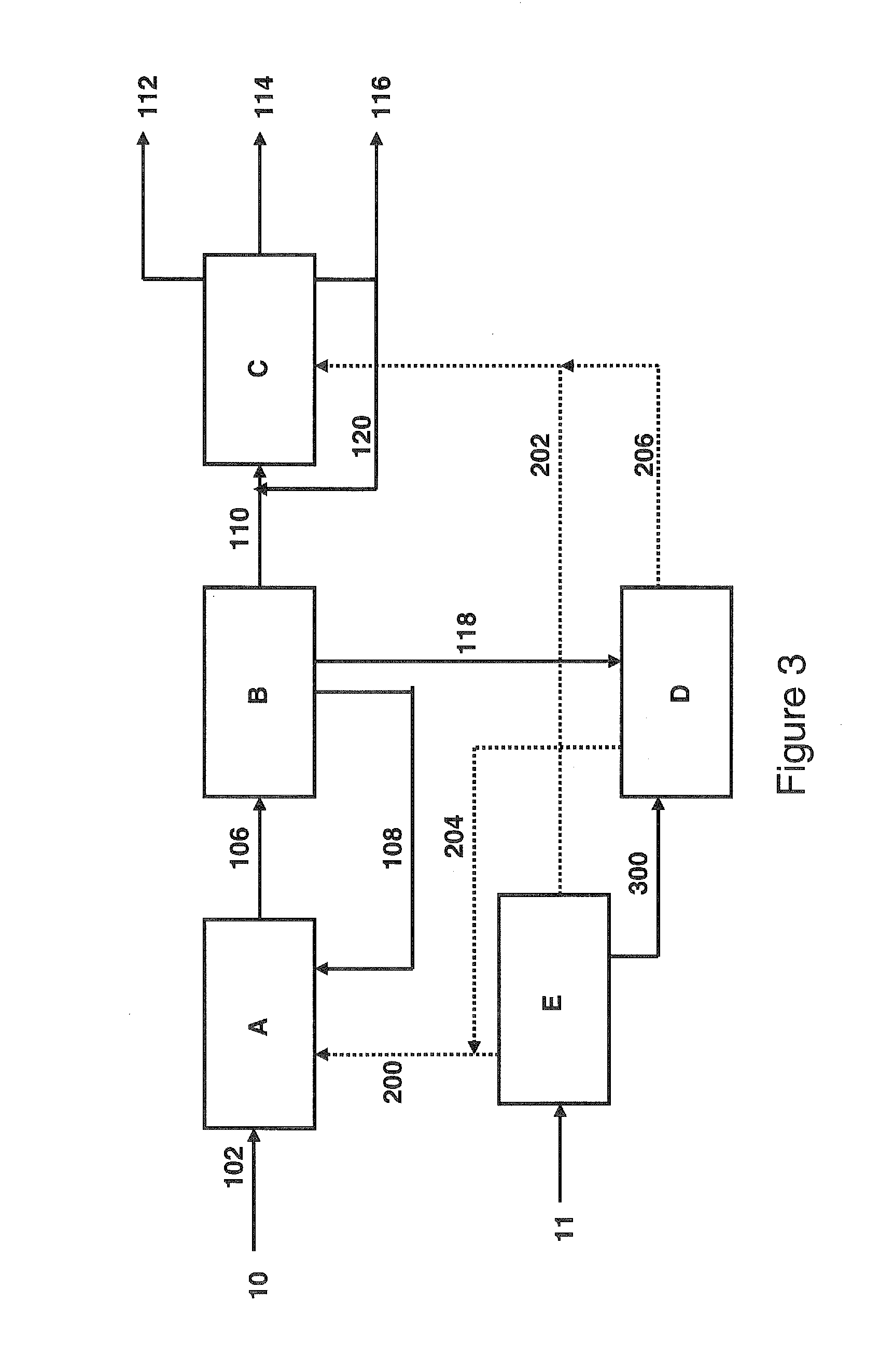
The issue for the industrial development of the direct liquefaction of carbon material is therefore to limit the greenhouse gas e

Method used


Image

  • Carbon material conversion process comprising two liquefaction stages in a boiling bed in the presence of hydrogen generated by non-fossil sources
  • Carbon material conversion process comprising two liquefaction stages in a boiling bed in the presence of hydrogen generated by non-fossil sources
  • Carbon material conversion process comprising two liquefaction stages in a boiling bed in the presence of hydrogen generated by non-fossil sources

Examples


example 1

Not in Accordance with the Invention

[0129]Coal of the Illinois No. 6 type was pretreated, then having an ash content close to 6% by weight of dry coal. The coal is then subjected to a two-stage liquefaction according to the H-Coal TS® process. The operating conditions of the liquefaction appear in Table 1. The hydrogen that is necessary to the liquefaction originates from a gasification of coal. The performance levels of the overall coal liquefaction chain are described in Table 3.

TABLE 1Operating Conditions of the Two-Stage LiquefactionCatalystNiMo / AluminaTemperature of Reactor R1 (° C.)410Temperature of Reactor R2 (° C.)440Pressure, MPa17VVH of R1 (kg / h of Dry Coal / kg of1.2Catalyst)VVH of R2 (kg / h of Dry Coal / kg of1.2Catalyst)Input H2 (Nm3 / kg of Dry Coal)2.8Liquid / Carbon Recycling1.1

[0130]According to Table 3, the direct liquefaction process H-Coal TS® produces 3.9 barrels of liquid hydrocarbons (LPG+naphtha+diesel) per ton of dry coal without ash. This value integrates the produc...

example 2

According to the Invention

[0132]The liquefaction of Example 1 was repeated under the same operating conditions (Table 1). The hydrogen originates from electrolysis of water using electricity generated by a nuclear power plant. The 388° C.+ fraction, obtained after the separation of the effluent from the liquefaction and representing approximately 12% by weight of the coal liquefiers (organic fraction+undissolved coal), is not upgraded as fuel in this example. It is subjected to combustion (or oxycombustion by using the O2 that is produced by electrolysis), then producing heat and CO2.

[0133]The performance levels of the liquefaction that use hydrogen generated by a non-fossil source are synthesized in Table 3.

TABLE 3Performance Levels of the Direct Pathway of Liquefaction of Coal for theProduction of Fuels - H-Coal TS ® Process - Addition of Hydrogenfrom Fossil and Non-Fossil SourcesExample 1Example 2Hydrogen SourceGasificationElectrolyzerCarbon Feedstock for100100Liquefaction andGas...


PUM


Abstract

A process for converting carbon material into fuel bases comprising two liquefaction stages in the presence of hydrogen in a boiling-bed reactor containing a supported catalyst and integrating a hydrogen production stage generated by non-fossil sources that do not emit CO2. The hydrogen production stage comprises the gasification of biomass and/or the decomposition of water, hydrochloric acid, hydrogen chloride or hydrogen sulfide by thermal, electrolytic, chemical or biological processes. The thus produced hydrogen is sent into at least one of the liquefaction stages.

Description

[0001]This invention relates to a process for direct liquefaction of carbon material in a boiling bed in the presence of hydrogen including a stage for producing hydrogen generated by non-fossil sources and produced without CO2 emissions.[0002]The transportation sector is a major consumer of energy and today essentially depends on the non-renewable resource of petroleum. On the environmental plane, the combustion of fuels greatly contributes to greenhouse gas (GHG) emissions, in particular CO2. Within a context of climate change and petroleum dependence, it is therefore necessary to diversify fuels. The alternatives to the use of petroleum are potentially numerous: natural gas, coal, biomass, and the following energies: hydraulic, wind, solar, marine or nuclear.[0003]Taking into account the abundant coal reserves, an attractive alternative is the liquefaction of coal for the production of fuel bases. The liquefaction of coal that is more known under the English term “Coal-to-Liquids...

Claims


Application Information

Patent Timeline
IPC IPC(8): C10L1/00C10G1/08
CPCC01B3/04C01B3/042C01B3/22C01B2203/0277C01B2203/0283C01B2203/0415C01B2203/0475C10G1/006C10G1/06C10G1/083C10G49/007Y02C10/04C10J2300/093C10J2300/0916Y02E60/364C10G3/45C10G3/46C10G3/50C10G2300/1011C10G2400/04C10G2300/1014C10G2300/1074C10G2300/4081C10G2300/805C10G2400/02C10G2400/06C10G2400/08Y02P20/134Y02P20/145Y02P30/20Y02P20/133Y02P30/30Y02E60/36Y02P30/00Y02C20/40
Inventor BABE, CELINEHUYGHE, RAPHAELQUIGNARD, ALAINWEISS, WILFRIED
Owner INST FR DU PETROLE
Why Eureka
Try Eureka