Flocculation-magnetic separation system
- Summary
- Abstract
- Description
- Claims
- Application Information
AI Technical Summary
Benefits of technology
Problems solved by technology
Method used
Image
Examples
embodiment 1
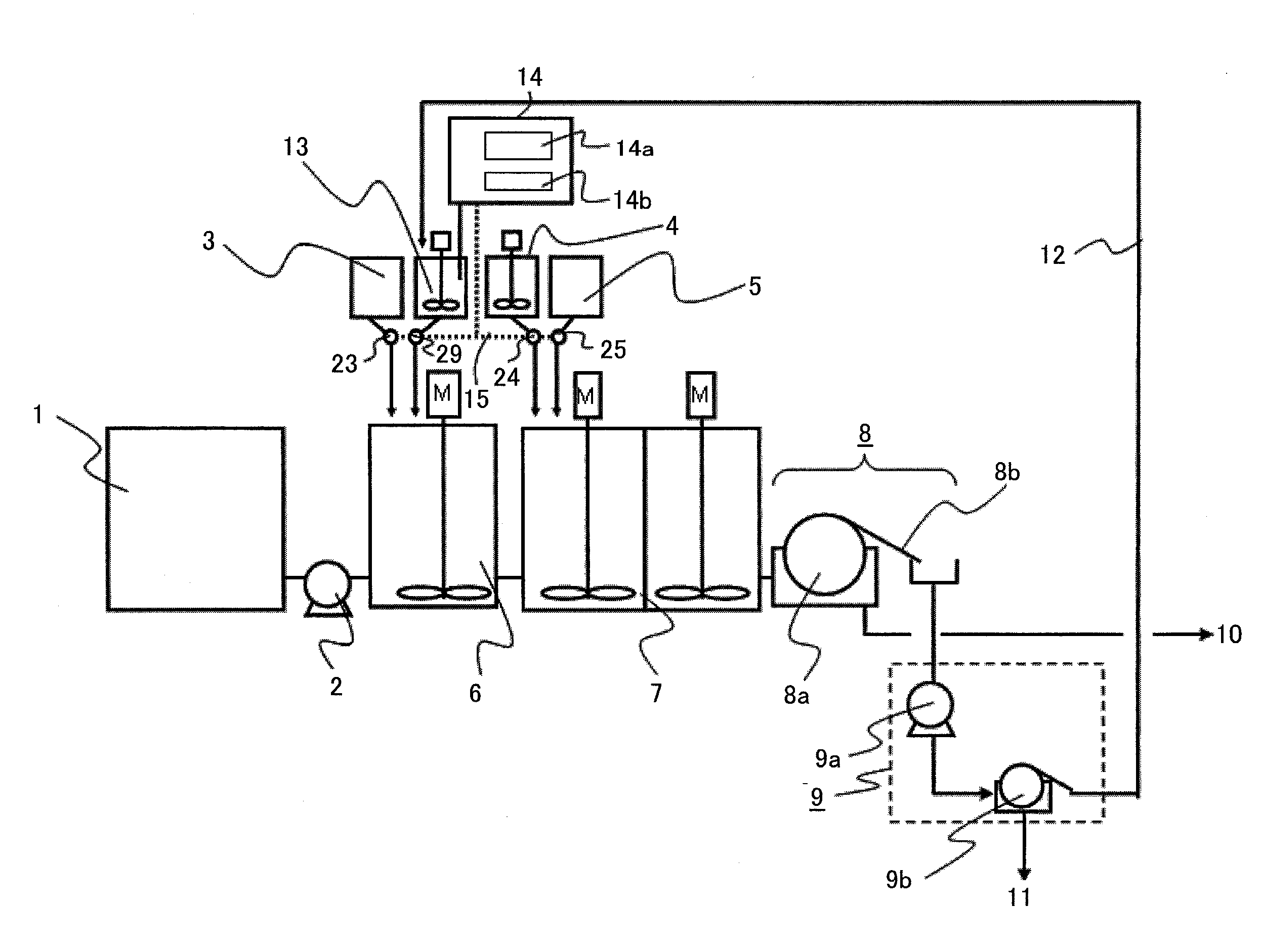
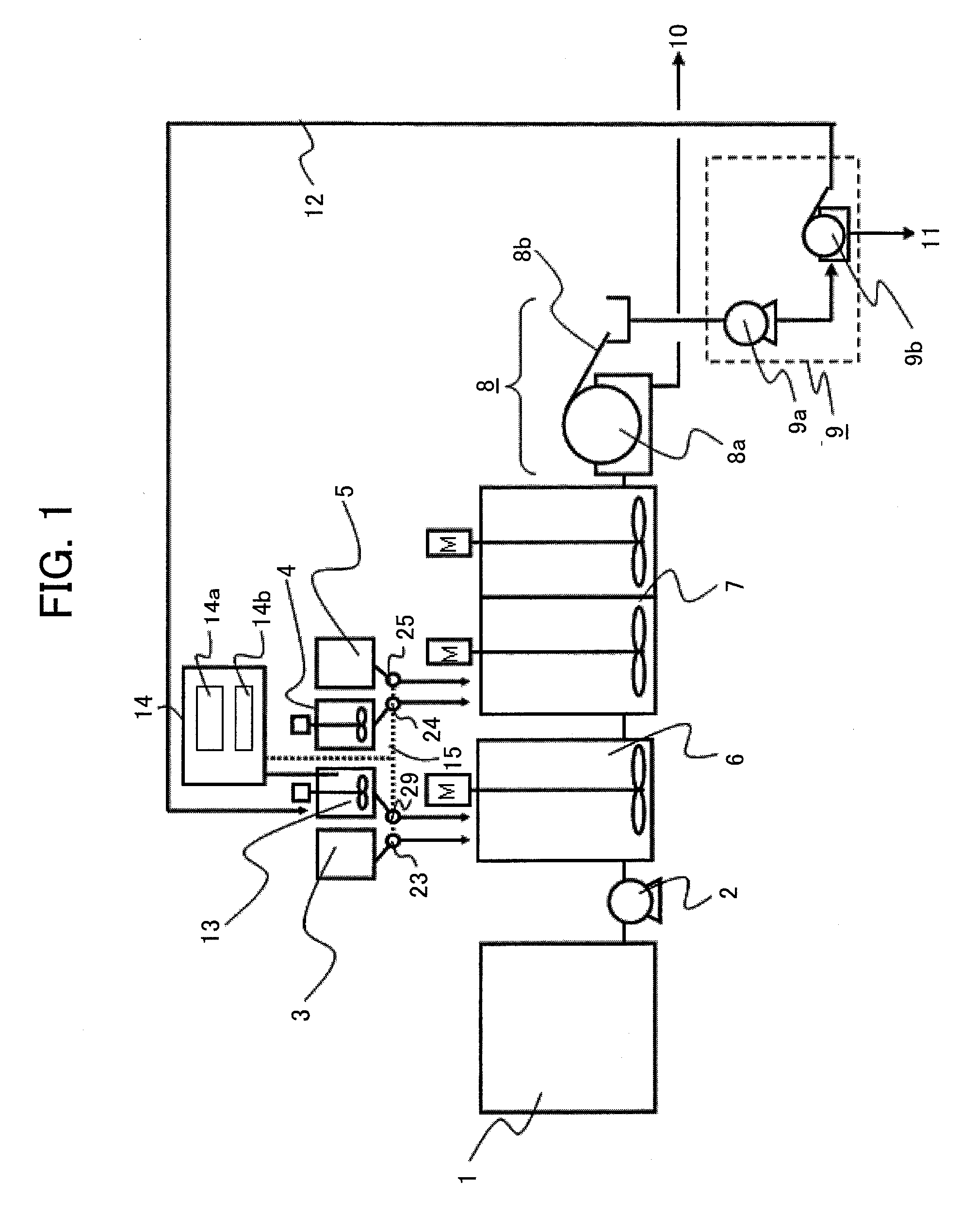
[0024]FIG. 1 is a schematic view of a structure of an embodiment 1 according to the present invention. Reference numeral 1 denotes a raw water tank for storing wastewater that becomes water to be treated, reference numeral 2 designates a raw water pump for sending the wastewater in the tank 1 to a flocculation section 6, and reference numeral 3 denotes a flocculant agent tank for storing new inorganic flocculant agents. Reference numeral 4 denotes a magnetic powder tank for storing new magnetic powders, reference numeral 5 designates a polymer flocculant agent tank for storing polymer flocculant agents, reference numeral 6 denotes a first flocculation section of a quick-speed agitating vessel, and reference numeral 7 designates a second flocculation section of a moderate-speed agitating vessel communicatingly connected to a downward stream side of the flocculation section 6.
[0025]The wastewater is sent to the flocculation section 6 from the tank 1. The inorganic flocculant agents in...
embodiment 2
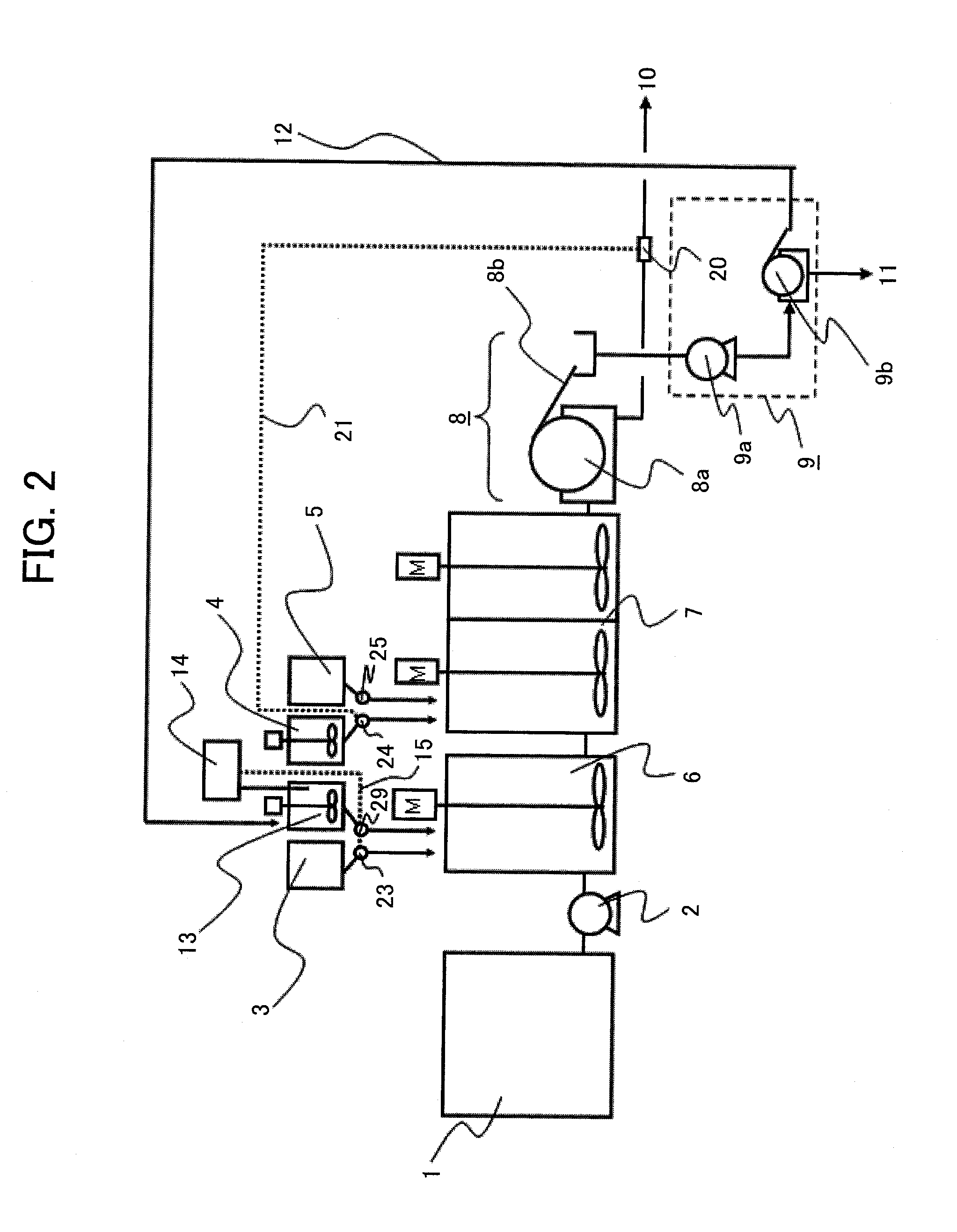
[0036]FIG. 2 is a schematic view of a structure of an embodiment 2 according to the present invention. This embodiment is different from the embodiment 1 shown in FIG. 1 in that the control of the discharge quantity of the magnetic powder pump 24 is not carried out based on the physical quantity of the magnetic materials in the recovered magnetic material tank 17 but is carried out by a signal 21 from a turbidity meter or a suspended solid substance-concentration meter 20 which is provided in the line for the treated water 10.
[0037]The addition amount of the magnetic powders exerts a great influence on the magnetic separation performance rather than the flocculation performance, so that it may be determined according to information on the quality of the treated water immediately after the magnetic separation process. In this case, when the value of the turbidity meter or the suspended solid substance-concentration meter 20 exceeds a predetermined threshold (high turbidity) and deter...
embodiment 3
[0039]FIG. 3 is a schematic view of a structure of an embodiment 3 according to the present invention. This embodiment is different from the embodiment 2 shown in FIG. 2 in that as the physical quantity based on the recovered magnetic materials, the magnetic materials in the recovered magnetic material tank 13 are not measured and one or more of turbidity in the flocculation section 6, particle diameters, and the zeta potential are measured by a control section 22. The control section 22 has the same structure as the control section 14 of the embodiment 1 does, makes a comparison between the measured physical quantity and the data of an internal table, and controls the discharge quantities of the flocculant agent injection pump 23 and of the recovered magnetic material injection pump 29 by the signal 19 on the basis of the comparison result.
[0040]The wastewater from the raw water tank 1 changes in the state of the substances to be eliminated, with the passage of time, and it is nece...
PUM
| Property | Measurement | Unit |
|---|---|---|
| Force | aaaaa | aaaaa |
| Zeta potential | aaaaa | aaaaa |
| Turbidity | aaaaa | aaaaa |
Abstract
Description
Claims
Application Information
 - R&D
- Intellectual Property
- Life Sciences
- Materials
- Tech Scout
- Unparalleled Data Quality
- Higher Quality Content
- 60% Fewer Hallucinations
Browse by: Latest US Patents, China's latest patents, Technical Efficacy Thesaurus, Application Domain, Technology Topic, Popular Technical Reports.
© 2025 PatSnap. All rights reserved.Legal|Privacy policy|Modern Slavery Act Transparency Statement|Sitemap|About US| Contact US: help@patsnap.com


