Electric power converter, driving apparatus and electric power steering apparatus

a technology of driving apparatus and electric power steering, which is applied in the direction of electric generator control, dynamo-electric converter control, dynamo-electric gear control, etc., can solve the problems of increasing ripple electric current, noise and heat generation of capacitors, and deteriorating controllability of electric current by inverters, so as to reduce ripple electric current of capacitors and increase the adjustment range of switching on-off timing

Active Publication Date: 2012-03-01
DENSO CORP
View PDF6 Cites 64 Cited by
  • Summary
  • Abstract
  • Description
  • Claims
  • Application Information

AI Technical Summary

Benefits of technology

[0011]It is therefore an object of the present invention to provide an electric power converter that reduces ripple

Problems solved by technology

Further, when one inverter and a group of three winding wires corresponding to that inverter is designated as one system, the capacitor electric currents from two systems add up if charging and discharging due to PMW control by the inverters in the two systems occur at the same timing, thereby causing an increase of the ripple electric current.
The increase of the ripple electric current causes noise and heat generation of the capacitor.
Further, as the applied voltage on the inverter changes, the controllability of the electric current by the inverter deteriorates.
However, even after phase-shifting the PWM reference signals from each other in two systems, or even after shifting the neutra

Method used


Image

  • Electric power converter, driving apparatus and electric power steering apparatus
  • Electric power converter, driving apparatus and electric power steering apparatus
  • Electric power converter, driving apparatus and electric power steering apparatus

Examples


first embodiment

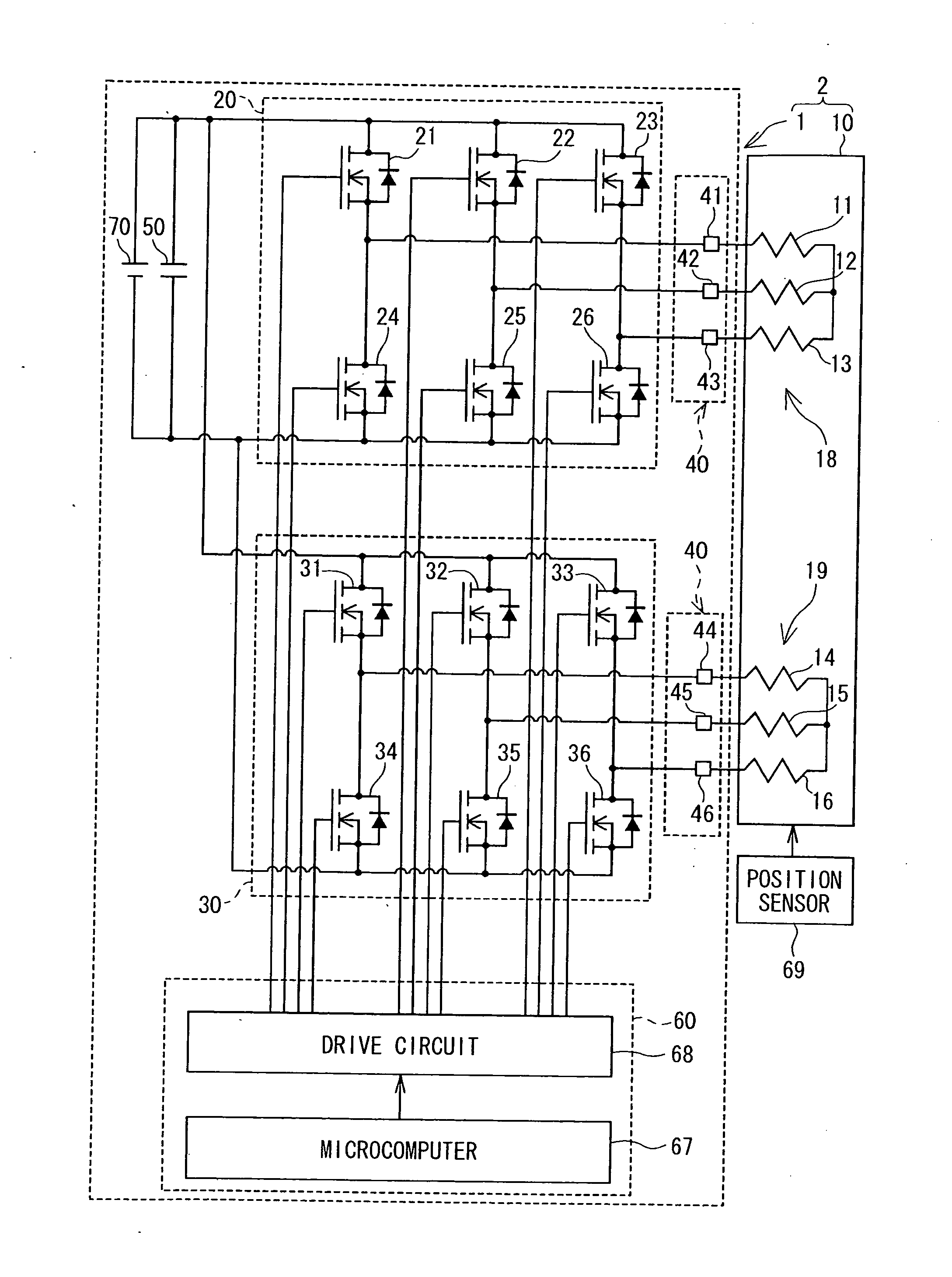
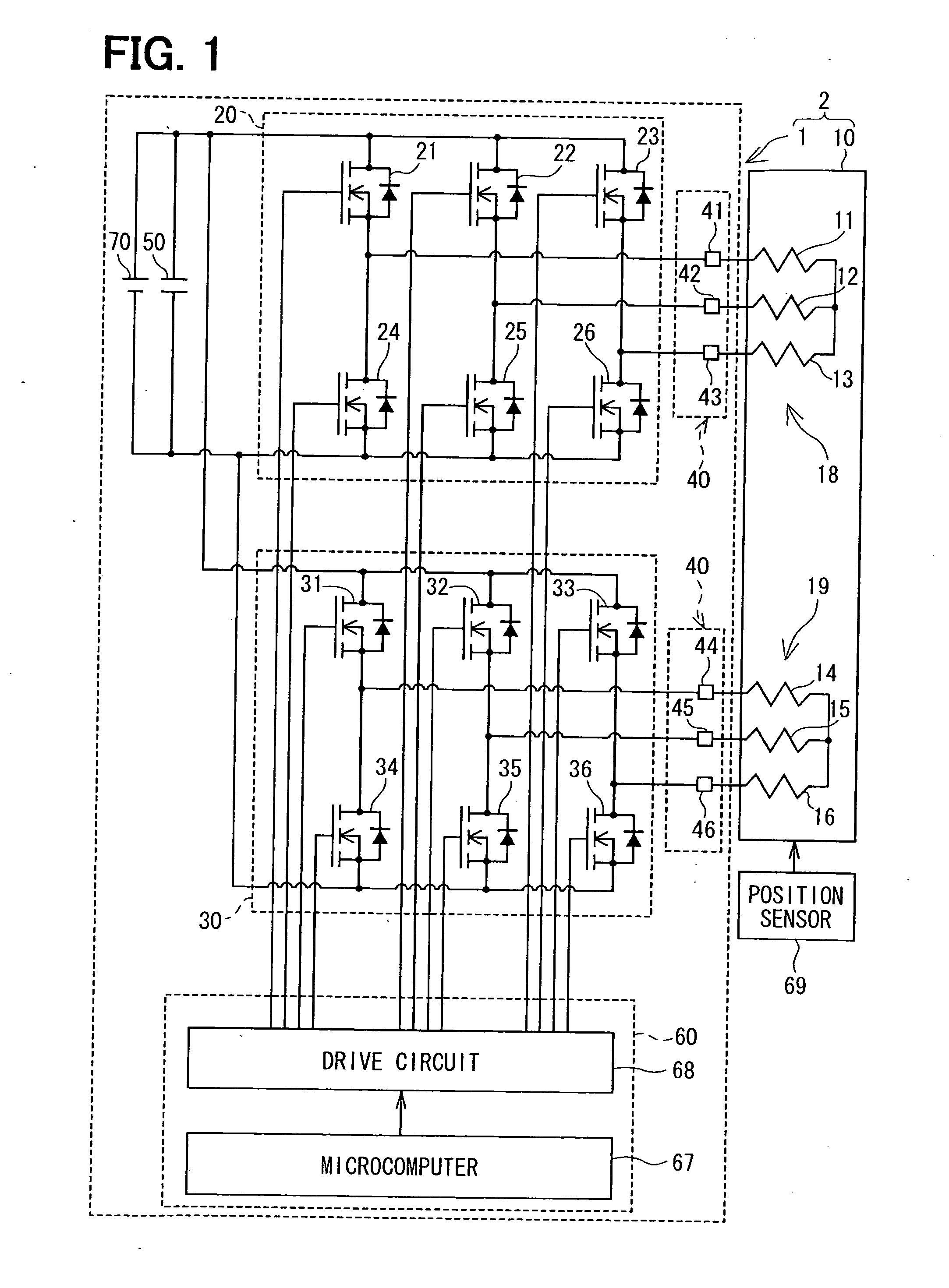
[0044]Referring to FIG. 1, an electric power converter 1 is provided to control driving of a three-phase motor 10 as a rotary electric machine. For example, the electric power converter 1 and the motor 10 form a driving apparatus 2, which is applied to an electric power steering apparatus to assist steering operation of a vehicle.

[0045]The electric power converter 1 includes two systems (#1 and #2) of inverter units, and drives two systems of winding wire combinations (i.e., groups) of the motor 10. Here, the term system is used to indicate a unit, which is a combination (i.e., a group) of one inverter unit and three-phase winding wires corresponding to one inverter unit.

[0046]The inverter unit and a group of winding wires in the first system (#1) are respectively designated as a first inverter unit 20 and a first winding wire group 18, and the inverter unit and a group of winding wires in the second system (#2) are respectively designated as a second inverter unit 30 and a second w...

second embodiment

[0120]The PWM control in the second embodiment is described with reference to FIGS. 13A to 14B. In the second embodiment, the modulation processor 653 performs the flatbed two-phase modulation process (cf. FIG. 9).

[0121]FIGS. 13A and 13B illustratively show as a comparative example against the second embodiment, in which the first duty instruction signal D21 and the second duty instruction signal D22 respectively having undergone the flatbed two-phase modulation process have the same phase.

[0122]The first duty instruction signal D21 and the second duty instruction signal D22 have the same amplitude and have the same phase, and the minimum values Dmin21, Dmin22 are substantially equal to the minimum value Rmin of the allowable duty output range, and the maximum values Dmax21, Dmax22 are only slightly greater than the center output value Rc. Further, a timing when the first duty instruction signal D21 takes the maximum value Dmax21 and a timing when the second duty instruction signal ...

third embodiment

[0135]In the third embodiment, the modulation processor 653 performs the flatbed two-phase modulation process (cf. FIG. 10).

[0136]FIGS. 15A and 15B illustratively show as a comparative example against the third embodiment, in which the first duty instruction signal D31 and the second duty instruction signal D32 respectively having undergone the flattop two-phase modulation process have the same phase.

[0137]The first duty instruction signal D31 and the second duty instruction signal D32 have the same amplitude and have the same phase, and the minimum values Dmin31, Dmin32 are substantially equal to the maximum value Rmax of the allowable duty output range, and the minimum values Dmin31, Dmin32 are only slightly smaller than the center output value Rc. Further, a timing when the first duty instruction signal D31 takes the minimum value Dmin31 and a timing when the second duty instruction signal D32 takes the minimum value Dmin32 overlap at every 60°.

[0138]FIG. 15B is an enlarged diagr...


PUM


Abstract

A control unit of an electric power converter, which is used in a three-phase motor having two winding wire systems, performs for a first duty instruction signal regarding a voltage applied to a first winding wire group a flatbed two-phase modulation process, and performs for a second duty instruction signal regarding a voltage applied to a second winding wire group a flattop two-phase modulation process. By phase-shifting the second duty instruction signal by 30° from the first duty instruction signal, a timing of maximum value of the first duty instruction signal is shifted from a timing of minimum value of the second duty instruction signal. Even when the maximum value is greater than a center output value and the minimum value is smaller than the center output value, overlapping of capacitor discharge is avoided, thereby reducing a ripple electric current.

Description

CROSS REFERENCE TO RELATED APPLICATION[0001]The present application is based on and claims the benefit of priority of Japanese Patent Application No. 2010-190438 filed on Aug. 27, 2010, the disclosure of which is incorporated herein by reference.FIELD OF THE INVENTION[0002]The present invention generally relates to an electric power converter for driving a three-phase rotary electric machine, a driving apparatus including the electric power converter, and an electric power steering apparatus using the driving apparatus.BACKGROUND INFORMATION[0003]Conventionally, pulse width modulation (PWM) control is used to control electric current for driving a multi-phase rotary electric machine. For example, if the multi-phase rotary electric machine is a three-phase motor, the electric current supplied to the three-phase motor is controlled by (a) comparing a voltage instruction signal regarding a voltage to be applied to respective winding wires of three phases with a PWM reference signal suc...

Claims


Application Information

Patent Timeline
IPC IPC(8): H02P27/04H02M7/44H02M7/48H02M7/493H02P6/06H02P6/08H02P6/28H02P21/00H02P21/05H02P21/22H02P23/04H02P27/06H02P27/08
CPCH02M1/14H02M7/493H02M2001/0009H02P25/22H02M2003/1586H02M1/0009H02M3/1586H02M1/0043
Inventor SUZUKI, TAKASHI
Owner DENSO CORP
Why Eureka
Try Eureka