Thermally-assisted recording head and magnetic recording system

a recording head and magnetic technology, applied in combination recording, data recording, instruments, etc., can solve the problems of difficult technical aspects, easy generation of optical coupling loss, and easy recording on a recording medium with high coercivity, so as to prevent the instability of propagating light, suppress the generation of stray light in the slider, and eliminate or reduce the non-propagating light

Inactive Publication Date: 2012-03-01
HITACHI LTD
View PDF4 Cites 10 Cited by
  • Summary
  • Abstract
  • Description
  • Claims
  • Application Information

AI Technical Summary

Benefits of technology

[0034]As described above, by eliminating or reducing the non-propagating light that is generated in the vicinity of the changing discontinuously portion in structure of the optical waveguide and likely to become stray light, it is possible to prevent the instability of propagating light caused by interference with stray light, and realize the stability behavior of a thermally-assist mechanism of the thermally-assisted magnetic recording head.
[0035]According to an aspect of the present invention, the generation of stray light in the slider can be suppressed, and the stable supply of light contributing to the thermally-assist mechanism can be realized. As a result, it is possible to realize the magnetic recording head in which stable thermal assisting is provided. Also, it is possible to stabilize the behavior of the magnetic disk device and improve the recording accuracy.

Problems solved by technology

However, this is difficult technically.
As a result, recording becomes easier on a recording medium with high coercivity where recording has been difficult with a related art magnetic head because of insufficient recording magnetic field strength.
When the beams from the LD enter an upper surface of the slider to be coupled to the optical waveguide, an optical coupling loss is generated, and there are inevitably some beams which do not become a propagating mode.
Coupling of the stray light to the optical waveguide is likely to cause interference with light in the propagating mode.
The interference between light beams different in phase causes instability of the light mode, resulting in spatial and temporal fluctuation in the intensity and the mode spot.
This instability of the mode causes instability in the supply of laser beams to the near-field generator provided in the vicinity of the ABS, thereby leading to instability in the near-field light to be generated and instability in the amount of heat required for recording onto a recording medium.
As a result, an expected thermal assisting cannot be achieved, and magnetic recording becomes impossible.
Therefore, preventing generation of such stray light or eliminating stray light is an important issue in stable thermally-assisted recording.
However, even if the number of optical coupling portions is reduced, the coupling loss of waveguide light is caused when light passes through the coupling points between components, thereby causing attenuation of the intensity of the waveguide light.
Consequently, a coupling portion inevitably exists between the semiconductor LD and the slider, and hence the optical loss is caused when light passes through the coupling portion.
However, some of the light strays around in the slider and becomes stray light.
When interference occurs, a designed waveguide light mode becomes difficult to forecast.
Further, the mode temporally fluctuates, causing instability in the mode of the light to be supplied to the near-field generator.
Such instability in the light to be supplied causes instability in the near-field light to be generated by the near-field generator, thereby preventing the amount of heat required for thermally-assisted recording from being controlled and transmitted to a recording medium.
As a result, magnetic recording state instability is caused.
As described above, the stray light causes not only the optical loss, but also the interference with the propagating-mode light propagating through the optical waveguide, resulting in instability in its original propagating mode because the stray light is different in phase from the propagating light mode.
Moreover, a recording magnetic pole, a coil for magnetizing the magnetic pole, a read sensor, a floating height control heater, wiring for supplying power thereto and the like are complexly disposed in the vicinity of the optical waveguide, thereby creating a situation in which light non-coupled to the optical waveguide is reflected and likely to become stray light.
Also, it is almost impossible in terms of mounting technology to couple the LD100 and the optical waveguide 111 without space therebetween.
However, this light is reflected by various structures existing in the slider 110 or a trailing edge surface of the slider 110 and likely to become stray light.
Interference between the waveguide light 204 propagating through the optical waveguide 111 and the stray light causes irregularities in the field of the waveguide light 204, leading to instability in the supply of light.
This can result in deterioration of the stability behavior of a thermally-assisted mechanism.
Otherwise, sufficient light is prevented from being supplied to the near-field generator 115, leading to significant reduction in the light conversion efficiency.
However, since the loss caused upon reduction of the light field spot size cannot be completely eliminated, the optical loss occurs.
When optical coupling or light spot size conversion is performed, it is impossible to completely eliminate light radiation caused by optical loss.
Therefore, how to suppress the generation of stray light has become an important issue.

Method used


Image

  • Thermally-assisted recording head and magnetic recording system
  • Thermally-assisted recording head and magnetic recording system
  • Thermally-assisted recording head and magnetic recording system

Examples


first example

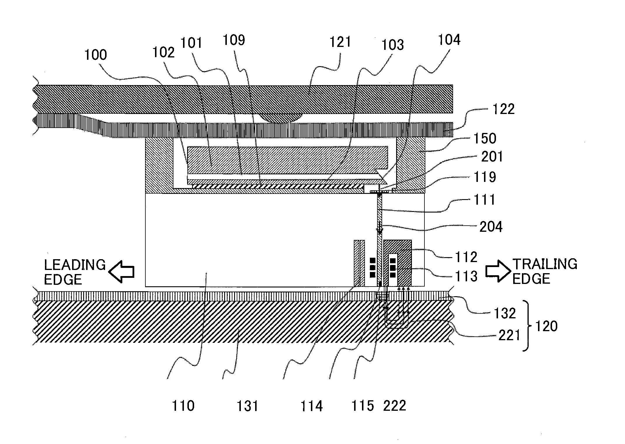
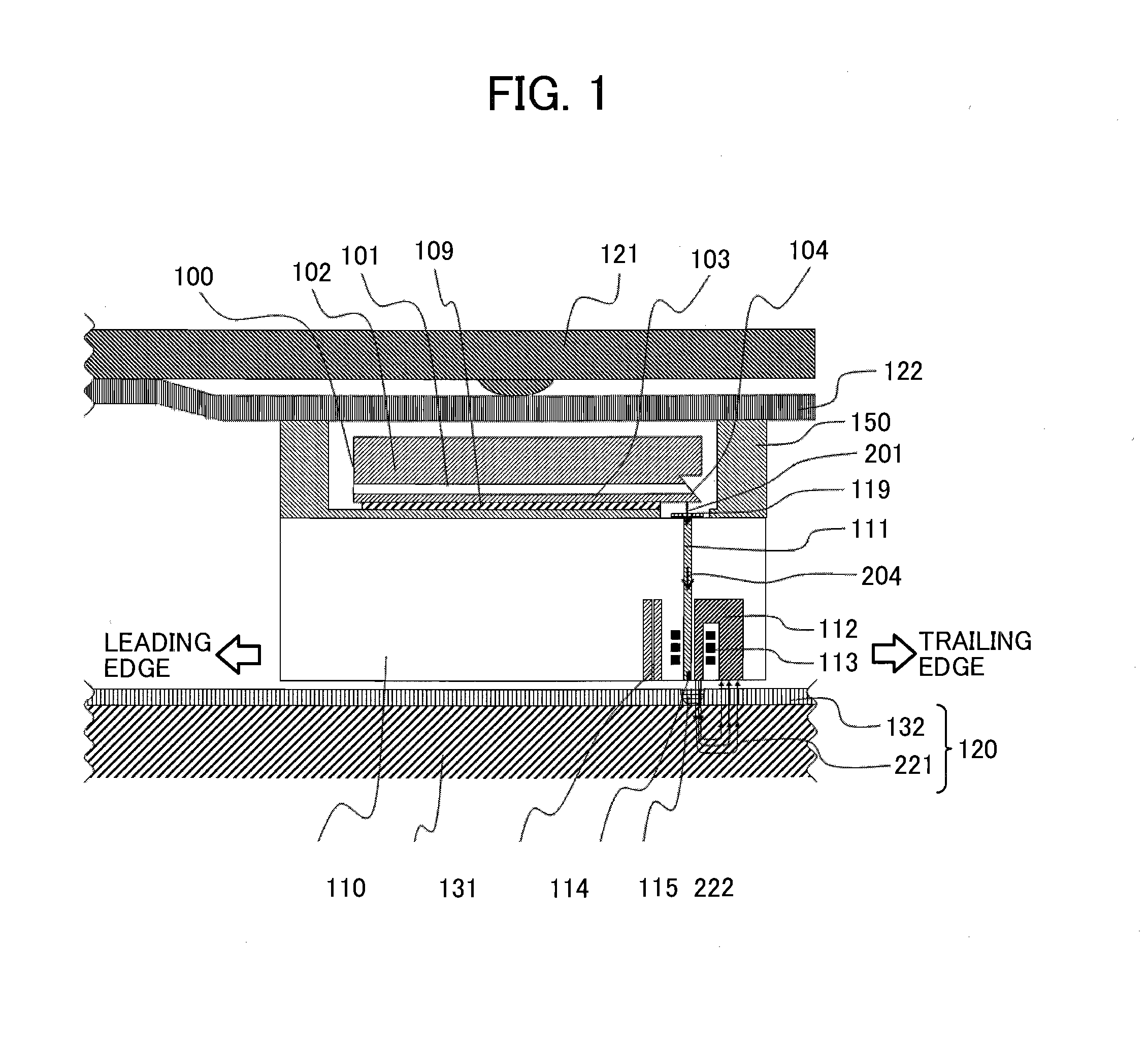
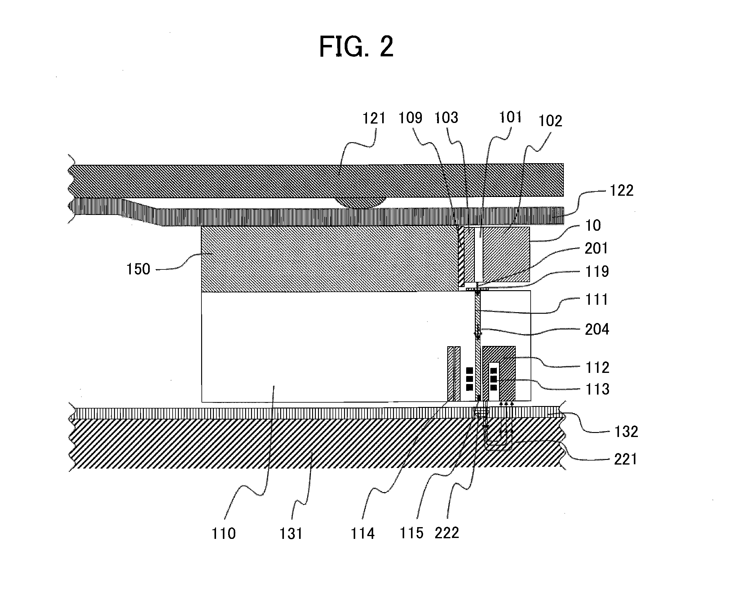
[0057]FIG. 10 is a schematic perspective view of an optical waveguide core and shield, a magnetic pole, a magnetizing coil, and a connecting terminal provided in a slider of a thermally-assisted magnetic recording head according to an another embodiment of the present invention. The optical waveguide core 111 is surrounded by the cladding 118. The annular light shield 300, serving as a laser beam absorber or reflector, is disposed in such a manner as to surround the periphery of the cladding 118. Also, a near-field generator 115 is disposed at a leading end of the optical waveguide core 111. The light propagating through the optical waveguide 111 is projected on the near-field generator 115 to be absorbed. A recording magnetic pole 112 is disposed in the vicinity of the near-field generator 115 to generate a recording magnetic field. The near-field light generated by the near-field generator 115 locally raises the temperature of a recording medium, and recording is performed in a th...

second example

[0060]FIG. 11 is a schematic perspective view of a magnetic disk device using a thermally-assisted magnetic recording head according to an another embodiment of the present invention.

[0061]A recording disk 402 rotates within a device case 400 with a spindle 403. An arm 405 is driven by a voice coil motor 401. A suspension 406 is attached to the arm 405. A thermally-assisted magnetic recording head 410 with the LD100 or with the LD10 mounted over the slider 110 is connected to the tip of the suspension 406.


PUM

PropertyMeasurementUnit
sizeaaaaaaaaaa
sizeaaaaaaaaaa
thicknessaaaaaaaaaa

Abstract

In a magnetic recording head including an optical waveguide for guiding a laser beam to a surface of a magnetic recording medium, a shield is provided in the vicinity of at least one portion changing discontinuously in structure of the optical waveguide to absorb or reflect non-propagating light leaking from the discontinuous portion to the outside of the optical waveguide.

Description

[0001]The present application claims priority from Japanese application serial No. 2010-192115, filed on (Aug. 30, 2010), the content of which is hereby incorporated by reference into this application.BACKGROUND OF THE INVENTION[0002]1. Field of the Invention[0003]The present invention relates to a thermally-assisted recording head for assisting magnetic recording with heat caused by a laser beam, and a magnetic recording system using the thermally-assisted recording head.[0004]2. Description of the Related Art[0005]A higher recording density is demanded of a magnetic disk device mounted in a computer, etc. as one of the information recording devices, in order to store a large amount of information without enlarging the device. In order to achieve a higher recording density in a magnetic disk device, a recording medium with high coercivity is used because of the necessity to stabilize minute recording bits. To record a recording medium with high coercivity, it is necessary to concen...

Claims


Application Information

Patent Timeline
Patent Type & Authority Applications(United States)
IPC IPC(8): G11B13/04
CPCG11B5/314G11B2005/0021G11B2005/001G11B5/6088
Inventor SHIMIZU, JUNICHIRO
Owner HITACHI LTD
Why Eureka
Try Eureka