

Optical display device having polarizing film
- Summary
- Abstract
- Description
- Claims
- Application Information
AI Technical Summary
Benefits of technology
Problems solved by technology
Method used
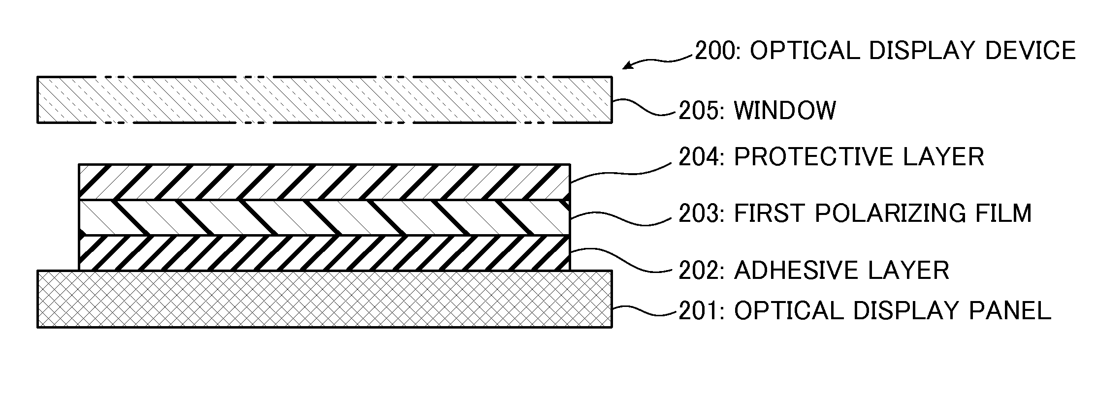
Image

Examples
example 1
[0137]A continuous web of substrate was prepared as a non-crystallizable ester type thermoplastic resin substrate comprising isophthalic acid-copolymerized polyethylene terephthalate copolymerized with 6 mol % of isophthalic acid (hereinafter referred to as “non-crystallizable PET”). The non-crystallizable PET has a glass transition temperature of 75° C. A laminate comprising the continuous web of non-crystallizable PET substrate and a polyvinyl alcohol (hereinafter referred to as “PVA”) layer was prepared in the following manner. By the way, PVA has a glass transition temperature of 80° C.
[0138]A non-crystallizable PET substrate having a thickness of 200 nm was prepared, and a PVA aqueous solution having a PVA concentration of 4 to 5 wt % was also prepared by dissolving a PVA powder having a polymerization degree of 1000 or more and a saponification degree of 99% or more in water. Then, the PVA aqueous solution was applied to the 200 μm-thick non-crystallizable PET substrate, and d...
example 2
[0147]In the Example 2, as with the Example 1, a 7 μm-thick PVA layer was formed on a non-crystallizable PET substrate to form a laminate, and then the laminate including the 7 μm-thick PVA layer was subjected to preliminary in-air stretching and stretched at a stretching ratio of 1.8 to form a stretched laminate, whereafter the stretched laminate was immersed in a dyeing solution containing iodine and potassium iodide and having a temperature of 30° C. to form a dyed laminate including an iodine-absorbed PVA layer. Differently from the Example 1, a process in the Example 2 additionally comprises a cross-linking step. The cross-linking step is designed to immerse the dyed laminate in a cross-linking boric acid aqueous solution at a temperature of 40° C., for 60 seconds, so as to allow PVA molecules of the iodine-absorbed PVA layer to be subjected to cross-linking. The cross-linking boric acid aqueous solution in this step was set to contain 3 weight parts of boric acid with respect ...
example 3
[0151]In the Example 3, as with the Example 1, a 7 μm-thick PVA layer was formed on a non-crystallizable PET substrate to form a laminate, and then the laminate including the 7 μm-thick PVA layer was subjected to preliminary in-air stretching and stretched at a stretching ratio of 1.8 to form a stretched laminate. Differently from the Example 1, a process in the Example 3 additionally comprises an insolubilization step. The insolubilization step is designed to immerse the stretched laminate in a boric acid insolubilizing aqueous solution at a solution temperature of 30° C., for 30 seconds, so as to insolubilize a PVA layer included in the stretched laminate and having oriented PVA molecules. The boric acid insolubilizing aqueous solution in this step was set to contain 3 weight parts of boric acid with respect to 100 weight parts of water. A technical effect expected of the insolubilization step in the Example 3 is to prevent the PVA layer included in the stretched laminate from bei...
PUM
| Property | Measurement | Unit |
|---|---|---|
| Thickness | aaaaa | aaaaa |
| Transparency | aaaaa | aaaaa |
| Phase | aaaaa | aaaaa |
Abstract
Description
Claims
Application Information