Nanostructure electrode for pseudocapacitive energy storage

Active Publication Date: 2012-03-08
GLOBALFOUNDRIES US INC
View PDF6 Cites 10 Cited by
  • Summary
  • Abstract
  • Description
  • Claims
  • Application Information

AI Technical Summary

Benefits of technology

[0007]A nanoporous templating substrate, which is an anodically oxidized alumina (AAO) substrate, is employed to form a pseudocapacitor having high stored energy density. A pseudocapacitive material is deposited conformally along the sidewalls of the AAO substrate by atomic layer deposition, chemical vapor deposition, and/or electrochemical deposition employing a nucleation layer. The thickness of the pseudocapacitive material on the walls can be precisely controlled in the deposition proc

Problems solved by technology

Increasing this area is not only difficult, but also produces only minimal increases in stored energy.
To date, this constraint has limited the energy density of an ultracapacitor to below 10 Wh/kg.
While pseudocapacitance (PC) can store about ten times more charge than a standard EDLC in theory, there are no commercial pseudocapacitors that have demonstrated anything remotely approaching this energy density level to this date.
The problem can be found in the microscopic nature of the electrode—the electrode must have a very large surface area in order to be able to take advantage of the potential for high energy density.
So far, all known methods for creating a PC electrode involve coating of a PC material ont

Method used


Image

  • Nanostructure electrode for pseudocapacitive energy storage
  • Nanostructure electrode for pseudocapacitive energy storage
  • Nanostructure electrode for pseudocapacitive energy storage

Examples


first embodiment

[0033]Referring FIGS. 3 and 4, a first exemplary structure according to the present disclosure is shown in a bird's eye view in FIG. 3 and in a vertical cross-sectional view in FIG. 4. The Z plane of FIG. 3 is the vertical cross-sectional plane of FIG. 4.

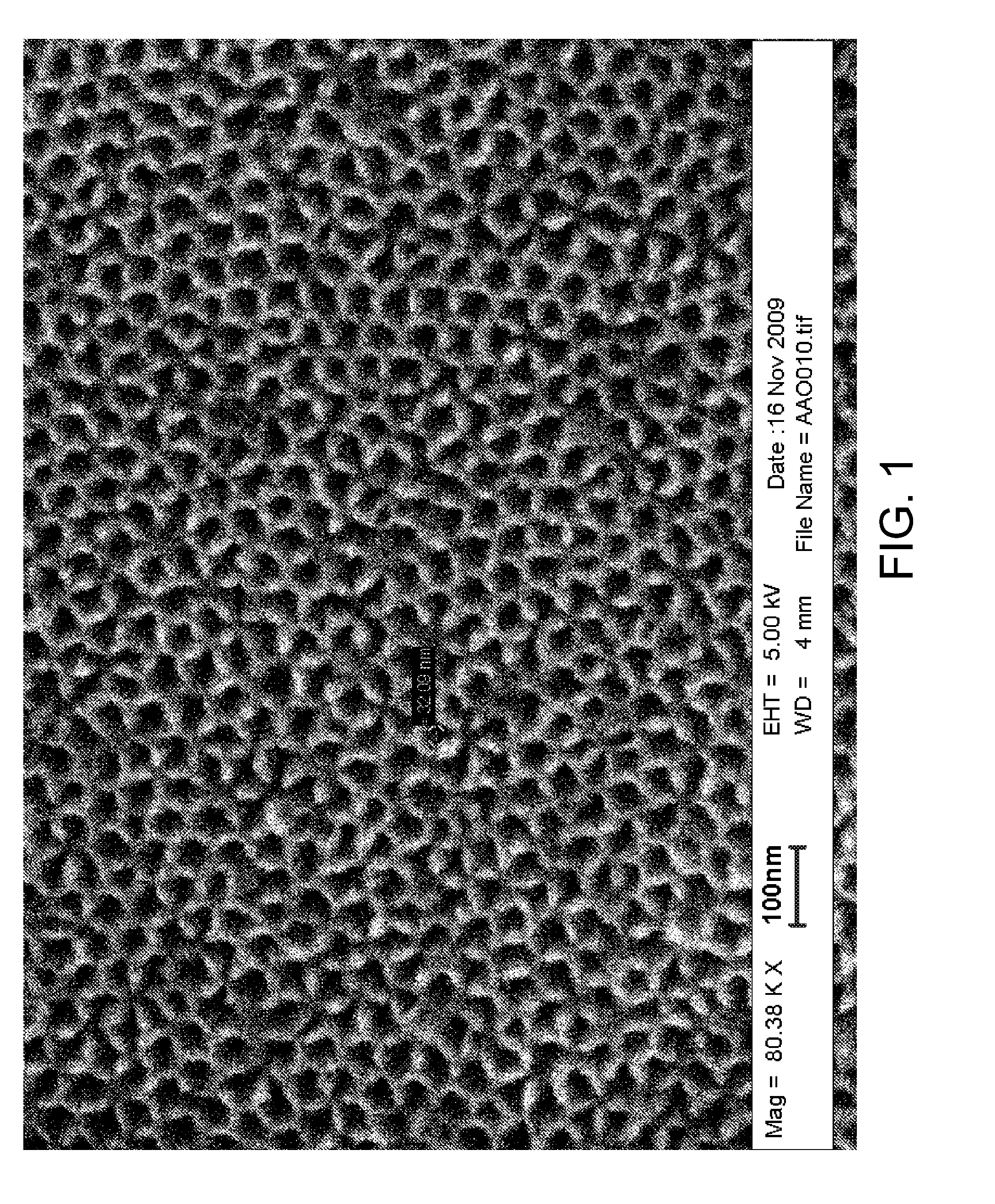
[0034]The first exemplary structure includes a stack of a conductive substrate 10 and an anodized aluminum oxide (AAO) substrate 20. The AAO substrate 20 is a sheet of aluminum foil that is anodically oxidized to be converted into aluminum oxide layer that includes a self-assembled array of vertical pores therein. An AAO substrate 20 can be formed employing methods known in the art. The AAO substrate 20 includes an array of “nanopores”21, which refers to pores having a diameter less than 1 micron. The diameter of individual nanopores 21 and the pitch of the array of nanopores 21 can be controlled by altering anodization parameters.

[0035]Typically, the diameter of each nanopore 21 is from 10 nm to 200 nm, although lesser and greater ...

third embodiment

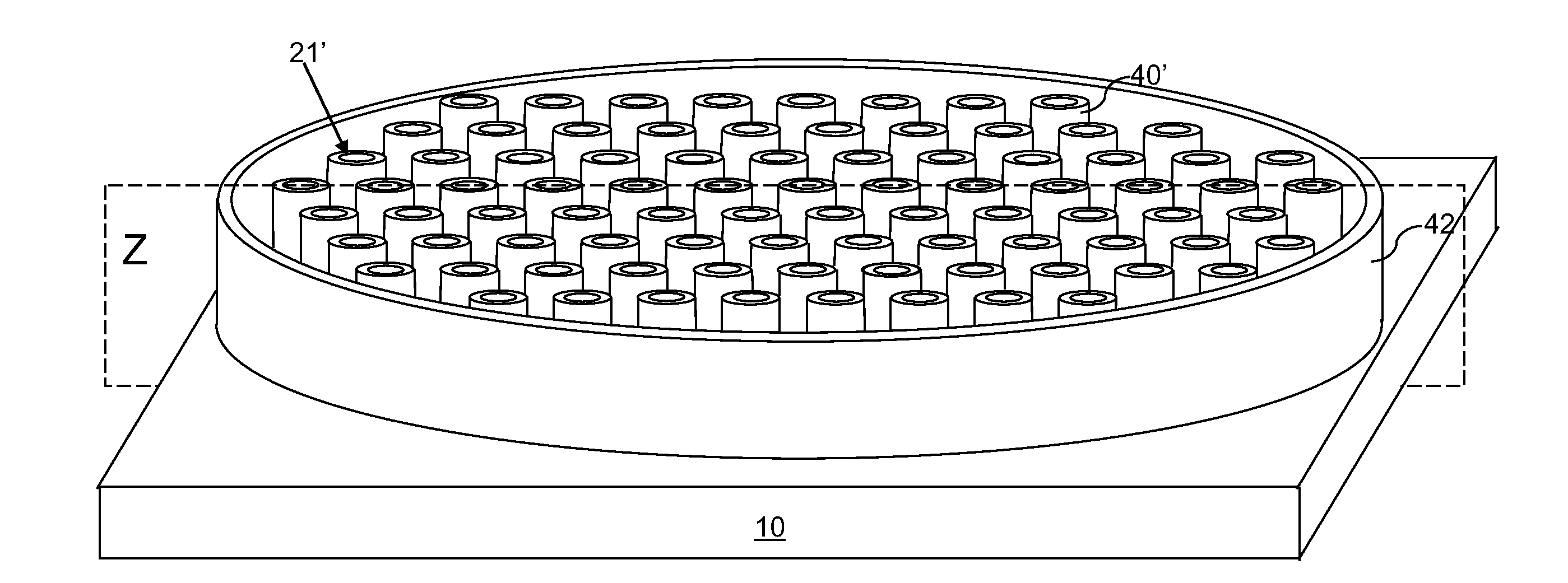
[0061]Referring to FIG. 17, a third exemplary structure according to the present disclosure can be derived from the second exemplary structure of FIGS. 11 and 12 by removing the topmost planar portion of the pseudocapacitive material layer 30L to expose the surfaces of the AAO substrate 20. Alternately, the third exemplary structure can be derived from the second exemplary structure of FIG. 10 by first removing the topmost planar portion of the pseudocapacitive material layer 30L to expose the surfaces of the AAO substrate 20 and then removing the disposable substrate 99 and the bottom portions of the pseudocapacitive material layer 30L. An assembly (20, 40′) of the AAO substrate 20 and a plurality of pseudocapacitive nanocylinders 40″ is formed. Each pseudocapacitive nanocylinder 40″ is a cylindrical tube that is topologically homeomorphic to a torus, and has an exposed inner vertical sidewall, an exposed top end surface with a hole therein, and an exposed bottom end surface with a...


PUM


Abstract

A nanoporous templating substrate, which is an anodically oxidized alumina (AAO) substrate, is employed to form a pseudocapacitor having high stored energy density. A pseudocapacitive material is deposited conformally along the sidewalls of the AAO substrate by atomic layer deposition, chemical vapor deposition), and/or electrochemical deposition employing a nucleation layer. The thickness of the pseudocapacitive material on the walls can be precisely controlled in the deposition process. The AAO is etched to form an array of nanotubes of the PC material that are cylindrical and structurally robust with cavities therein. Because the AAO substrate that acts as scaffolding is removed, only the active PC material is left behind, thereby maximizing the energy per mass. In addition, nanotubes may be de-anchored from a substrate so that free-standing nanotubes having randomized orientations may be deposited on a conductive substrate to form an electrode of a pseudocapacitor.

Description

BACKGROUND[0001]The present disclosure relates to an energy storage device, and particularly to an energy storage device including at least one nanostructure electrode having a large surface area of a pseudocapacitive material for pseudocapacitive energy storage, and methods of manufacturing the same.[0002]Ultracapacitors or electrochemical double layer capacitors (EDLC's) provide the highest energy density among commercially available devices employing capacitive energy storage. Although such EDLC's are capable of operation at considerably higher power than a battery, the energy density of even high performance EDLC's is lower than the energy density of high performance batteries by a factor of 10˜20. A traditional ultracapacitor consists of two electrodes that are fabricated from highly porous activated carbon sheets that provide very large surface area, which is typically on the order of 1000 square meters / gram of material. These porous activated carbon-based electrodes are immer...

Claims


Application Information

Patent Timeline
IPC IPC(8): H01G9/00B05D5/12
CPCH01G11/26Y02E60/13H01G11/46H01G11/36Y02P70/50H01G9/04H01G11/24H01G11/22
Inventor HAIGHT, RICHARD A.ROSSNAGEL, STEPHEN M.
Owner GLOBALFOUNDRIES US INC
Why Eureka
Try Eureka