Method for operating a regenerative heater

a regenerative heater and heater technology, applied in the field of regenerative heater operation, can solve the problems of uncompatibility of oxidizing gas fed to the regenerative heater during the heating cycle, unnecessarily reducing the temperature of checker bricks, and consuming time, so as to improve the ignition characteristics of tail gas and improve the burning of fuel

Active Publication Date: 2012-03-15
PAUL WURTH SA
View PDF10 Cites 3 Cited by
  • Summary
  • Abstract
  • Description
  • Claims
  • Application Information

AI Technical Summary

Benefits of technology

[0018]High calorific value gas may be fed into the first stream of fuel to improve the burning of the fuel in the burner of the regenerative heater. High calorific value ga

Problems solved by technology

Indeed, the oxidizing gas fed to the regenerative heater during the heating cycle is not compatible with the reducing gas fed through the regenerative heaters during the blowing

Method used


Image

  • Method for operating a regenerative heater
  • Method for operating a regenerative heater
  • Method for operating a regenerative heater

Examples


Embodiment Construction

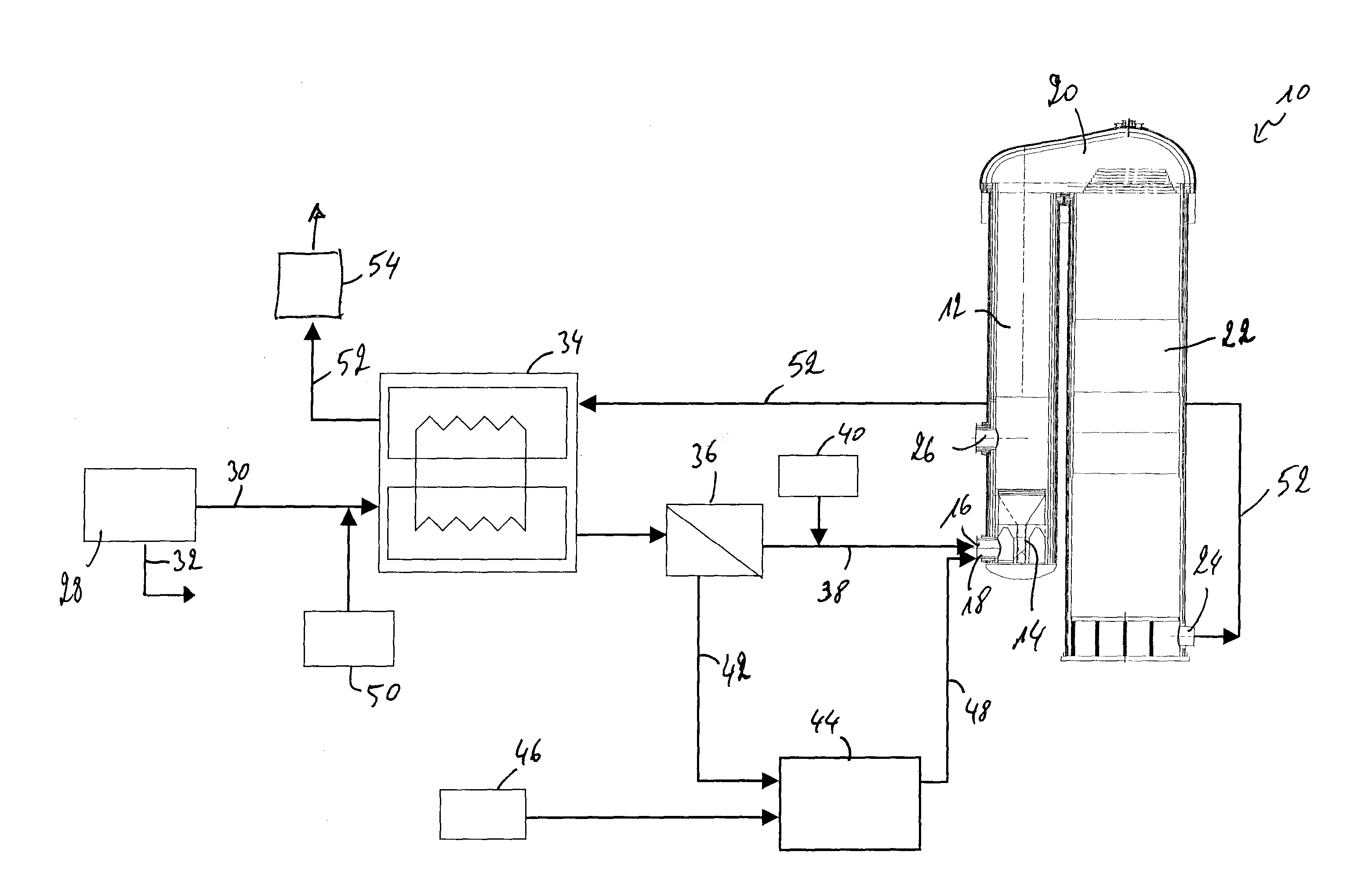
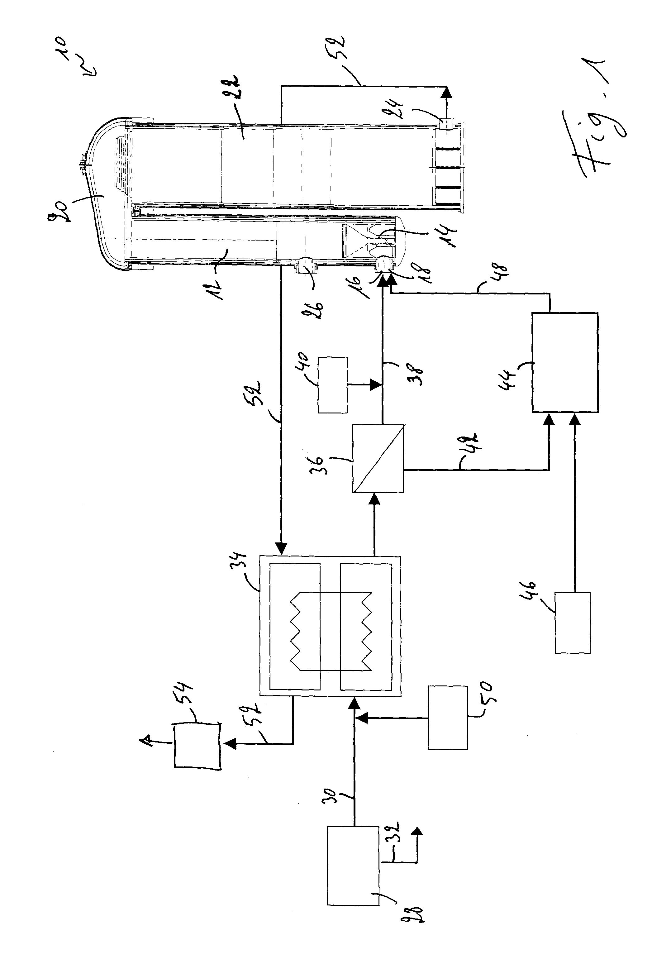
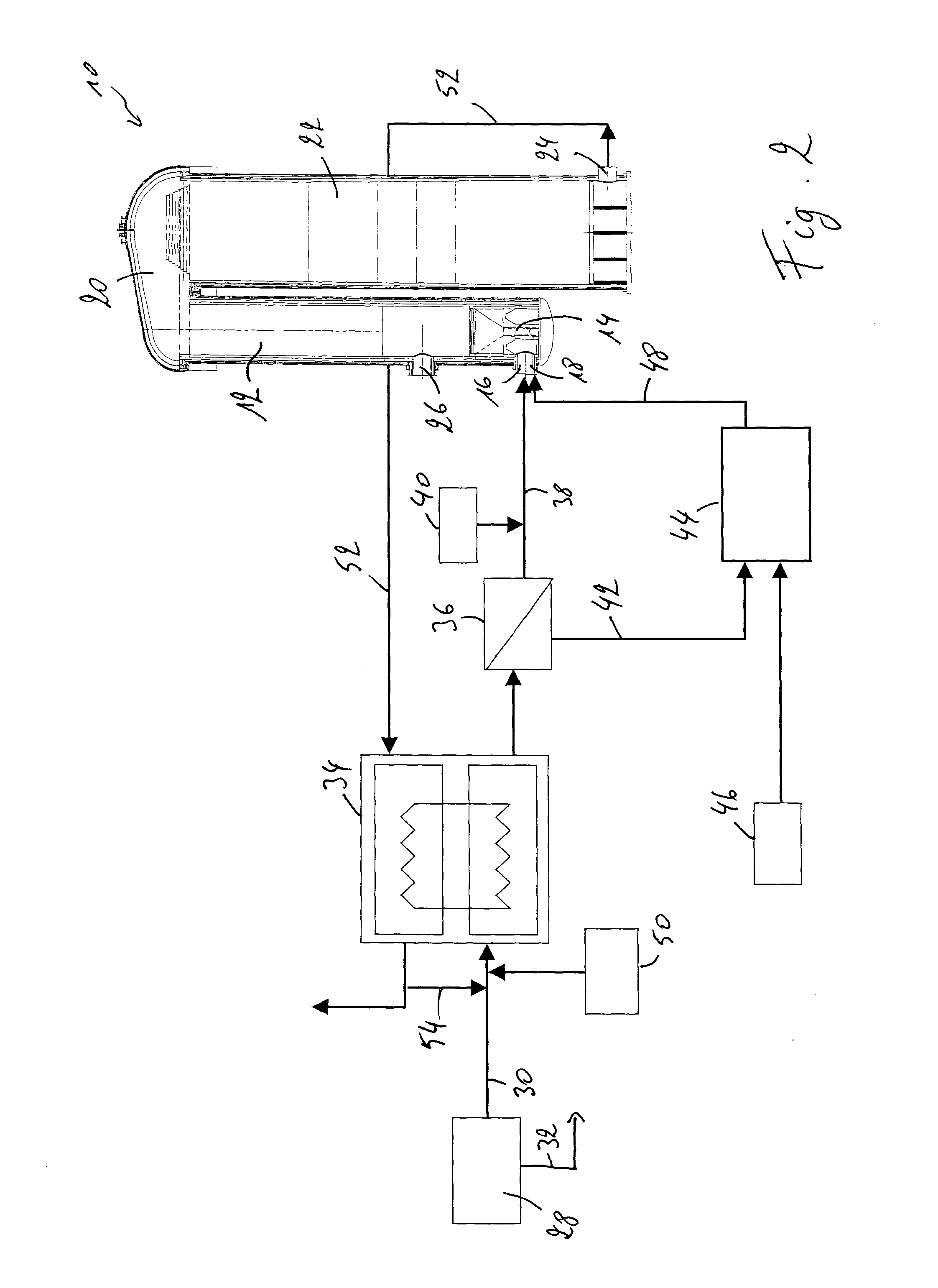
[0024]FIG. 1 shows a flow diagram of the heating cycle of the method for operating a regenerative heater according to a first embodiment of the present invention. FIG. 1 also shows a schematic view of a regenerative heater 10 in the form of a hot blast stove.

[0025]Such a regenerative heater 10 generally comprises a first chamber 12 with a burner 14 arranged therein. During the heating cycle, fuel and oxidizing gas is fed to the burner 14 via two gas inlets 16, 18. The fuel and oxidizing gas are ignited and their combustion creates hot flue gasses, which ascend into a cupola 20. The cupola 20 deviates the hot flue gasses and feeds them into a second chamber 22 comprising a series of heat storage means, generally in the form of checker bricks (not shown). The hot flue gasses finally exit the regenerative heater 10 through an opening 24 in the lower portion of the second chamber 22.

[0026]During the subsequent blowing cycle, process gas is blown into the second chamber 22 through the op...


PUM


Abstract

The present invention proposes a method for operating a regenerative heater (10), in particular a hot blast stove of a blast furnace, the regenerative heater (10) comprising a first chamber (12) and a second chamber (22), the first chamber (12) having a burner (14) arranged therein, the second chamber (22) comprising heat storage means. Such a method comprises a heating cycle wherein fuel and oxidizing gas are fed to the burner (14) of the first chamber (12) and allowed to burn and wherein hot flue gasses are led through the second chamber (22) to heat the heat storage means; and a blowing cycle wherein a process gas is fed through the second chamber (22) to pick up heat from the heat storage means. According to an important aspect of the present invention, the heating cycle comprises the steps of feeding a first stream (38) of fuel to the burner (14) of the regenerative heater (10); feeding a second stream (42) of fuel to a pre-combustion chamber (44); feeding oxygen (46) to the pre-combustion chamber (44); allowing the second stream (42) of fuel and the oxygen (46) to interact so as to form oxidizing gas (48); and feeding the oxidizing gas (48) to the burner (14) of the regenerative heater (10). At the end of the heating cycle, the supply of oxygen (46) to the pre-combustion chamber (44) is discontinued, while further feeding the second stream (42) of fuel to the pre-combustion chamber (44) and further feeding the first stream (38) of fuel to the burner (14).

Description

TECHNICAL FIELD[0001]The present invention generally relates to a method for operating a regenerative heater, such as a hot blast stove of a blast furnace. More particularly, the present invention relates to an improved heating cycle of such a regenerative heater.BACKGROUND[0002]Blast furnaces are generally fed with hot blast air received from a regenerative heater such as a hot stove or a pebble heater. Such a regenerative heater generally comprises a first column and a second column, fluidly connected at the top by a cupola. A burner is arranged in the lower portion of the first column for burning a fuel and an oxidizing gas. The hot flue gasses created by the burning rise through the first column towards the cupola where they are directed into the second column. The second column is filled with checker bricks for absorbing heat from the hot flue gasses. The flue gasses then exit the second column via an opening in the lower portion of the second column. After the heating cycle, t...

Claims


Application Information

Patent Timeline
IPC IPC(8): C21B9/04C21B9/14
CPCC21B9/14C21B9/04Y02P10/122C21B9/00
Inventor SIMOES, JEAN-PAUL
Owner PAUL WURTH SA
Why Eureka
Try Eureka