
Microporous Microfluidic Device

a microfluidic device and microporous technology, applied in the field of microfluidic devices, can solve the problems of difficult observation of microfluidic channels of devices, and achieve the effect of simple processes and gas transportation efficiency

Inactive Publication Date: 2012-03-22
CORNING INC
View PDF1 Cites 47 Cited by
  • Summary
  • Abstract
  • Description
  • Claims
  • Application Information

AI Technical Summary

Benefits of technology

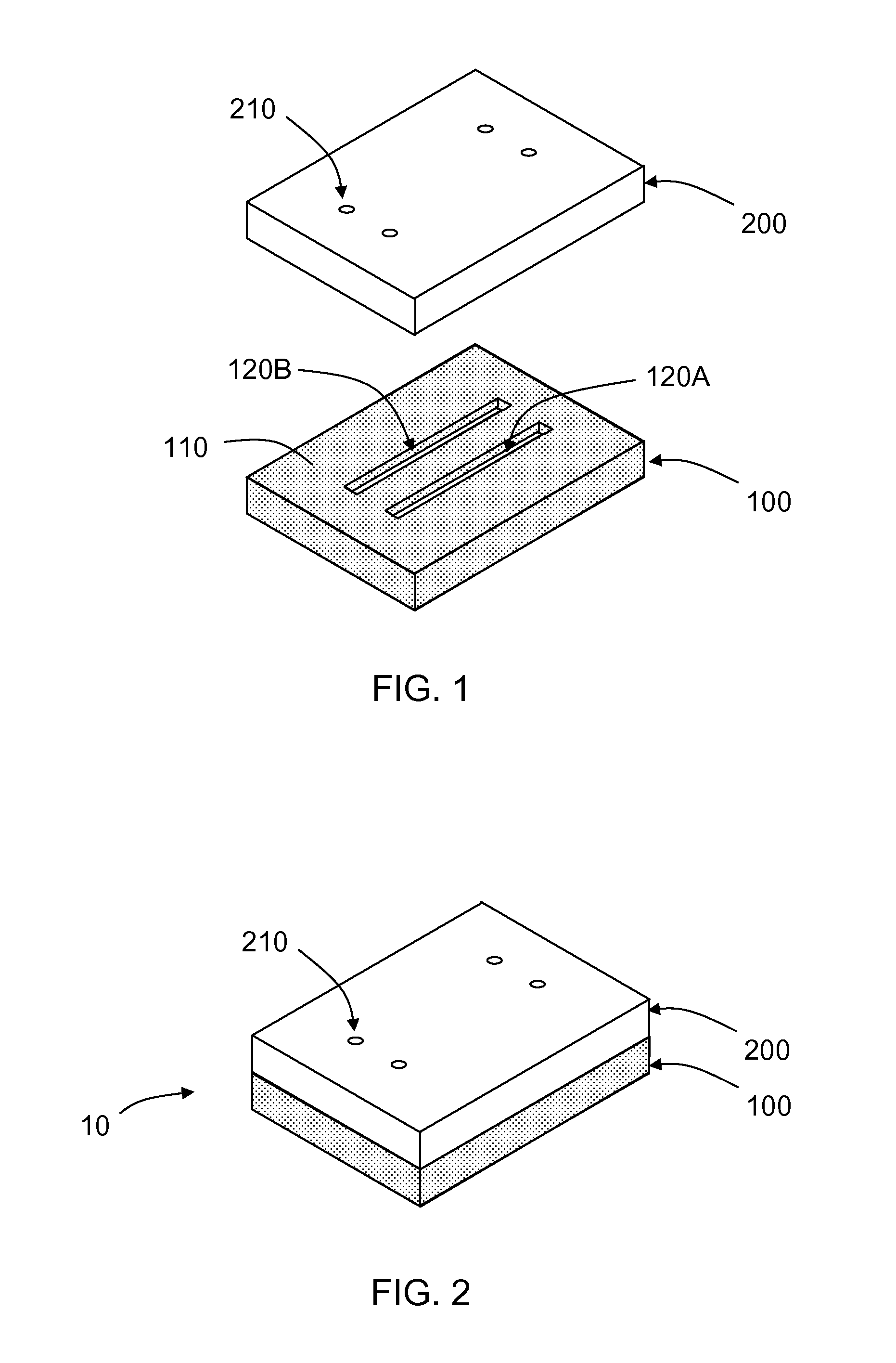
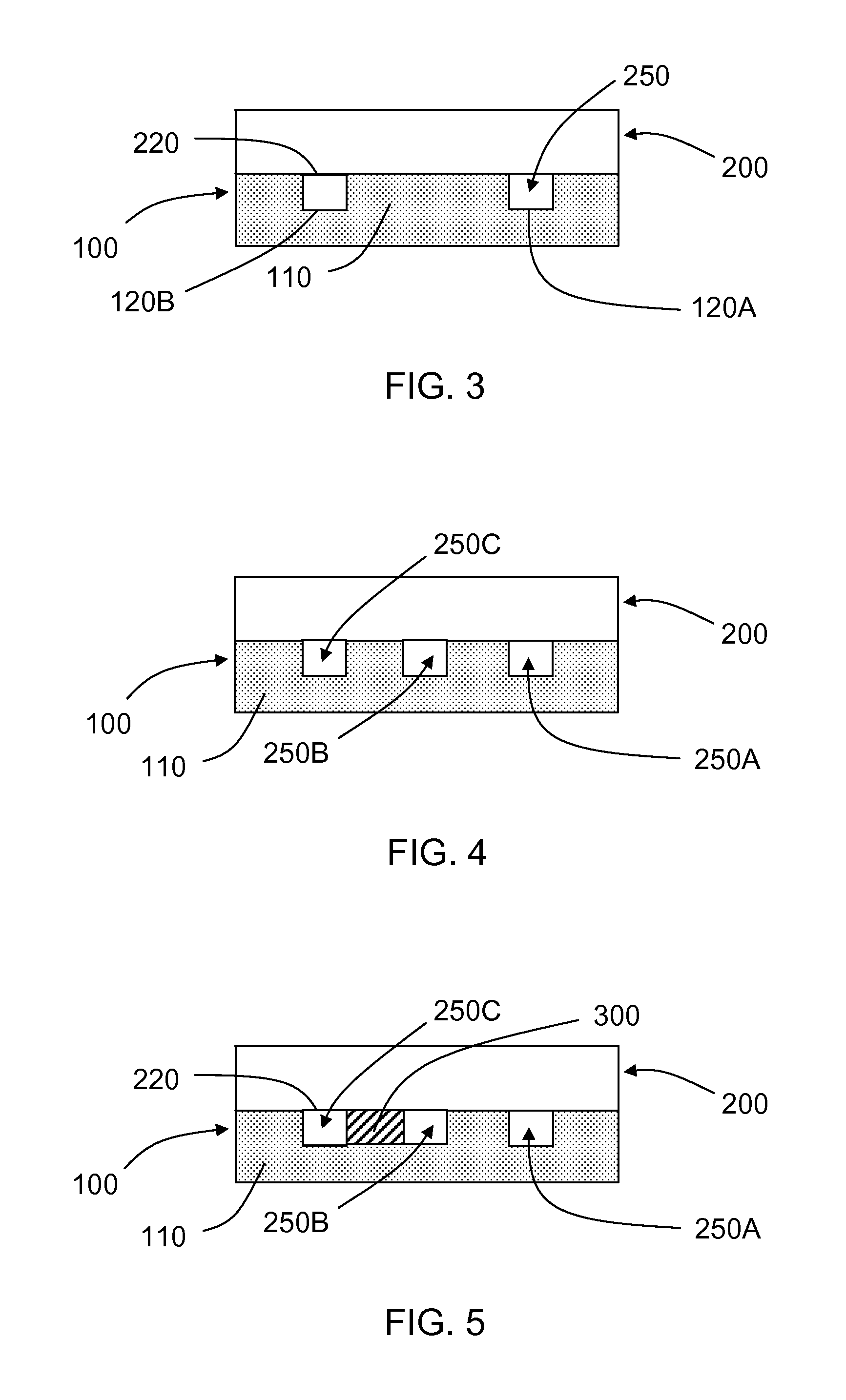
[0005]The present disclosure describes, among other things, microfluidic devices having microporous PDMS regions and an optically transparent portion that allows for viewing of the channels. Such microfluidic devices have the benefits of PDMS devices, which include ease of fabrication, rapid prototyping and reduced material costs, and the benefits of microporous devices, while still allowing visual observation of desired parts of the device while in use. In addition due to the hydrophobic nature of microporous PDMS, aqueous liquids but not gasses are prevented from passing through the microporous PDMS from one microfluidic conduit to another. Thus, selective diffusion of gasses can advantageously be achieved.
[0009]The devices and methods described herein may provide one or more advantages over prior microfluidic devices and methods. Using the methods described herein, a large range of pore sizes can be fabricated and tuned to a desired range for particular uses. Additionally, a highly interconnected microporous structure with different pore sizes can be fabricated in a single device by using different sizes of porogen in the pre-polymer before curing. Further, there is essentially no limitation on the physical size of the molded 3D interconnected microporous structures. Further, microporous microfluidic device in 3D configurations can be fabricated. Also, gas transportation efficiency through the 3D interconnected microporous structures is controllable because of large range of pore sizes can be used to fabricate the device. Additionally, device assembly can be performed efficiently, using simple processes. These and other advantages of the various embodiments of the devices and methods described herein will be readily apparent to those of skill in the art upon reading the disclosure presented herein.

Problems solved by technology

Perhaps this is because microporous PDMS tends to be optically opaque, which would make it difficult to observe microfluidic channels of the device.

Method used


Image

  • Microporous Microfluidic Device
  • Microporous Microfluidic Device
  • Microporous Microfluidic Device

Examples


example 1

Device Design, Fabrication and Assembly

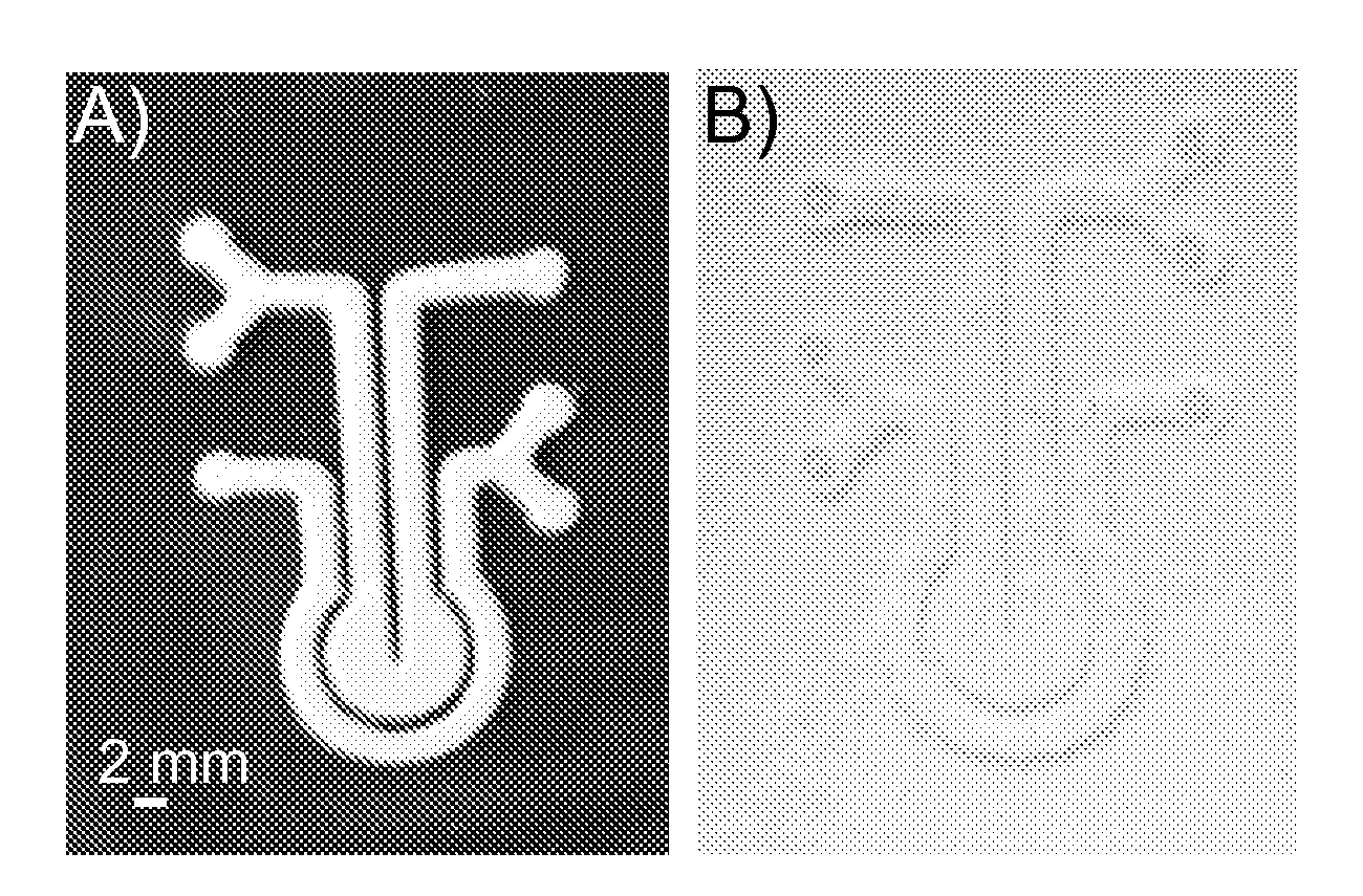
[0080]3D interconnected microporous PDMS microfluidic devices were developed to demonstrate the potential application of such devices via a gas absorption reaction. The device include of a 9.4 mm diameter inner circular chamber and a 2 mm wide outer circular channel separated by a 1 mm wide circular wall. Soft lithography was used to fabricate the microporous PDMS microfluidic device. Briefly, a microstructured mold was fabricated by stacking three custom cut 90 μm thick self-adhesive white vinyl sheets (Item # 699009; The Paper Studio®, Oklahoma City, Okla., USA) onto a glass slide (FIG. 9A). A PDMS prepolymer (10:1 w / w) (Sylgard® 184, Dow Corning Corporation, Midland, Mich., USA) mixed with pre-sieved sugar particles (1:2.5 v / v %) was cast onto the mold to a thickness of 2 mm and cured at 60° C. for overnight. The 2 mm thick microstructured PDMS replica was carefully peeled away. Then, the sugar particles in the microstructured PDMS replica w...

example 2

Acidification of Water by CO2 Gas

[0084]Bromothymol blue solution (Fluka® Analytical; Sigma-Aldrich® Corporation, St. Louis, Mo., USA) was used as a pH indicator solution to track the absorption of CO2 gas by water. As water absorbs CO2 gas, it reacts with the CO2 gas to form carbonic acid. Thus, the pH indicator solution should turn from blue (pH>7.6) to green (pH˜6.5-7.0) and then to yellow (pH2 gas was absorbed. The pH indicator solution with a pH of >7.6 (blue in color) was pipetted into the outer circular channel of the microporous PDMS microfluidic device (FIG. 12A) and was clearly retained inside the outer channel. The microporous structures remained dry during the experiment as indicated by their white appearance throughout the device (FIG. 12). Next, CO2 gas was generated inside a glass bubbler by dissolving dry ice in water. As the CO2 gas built up pressure inside the glass bubbler, it was directed through Tygon® tubing (Fisher Scientific, Pittsburgh, Pa., USA) into the inn...


PUM

PropertyMeasurementUnit
Water contact angleaaaaaaaaaa
Widthaaaaaaaaaa
Particle sizeaaaaaaaaaa

Abstract

A micro fluidic apparatus includes (i) a first conduit; (ii) a second conduit; and (iii) a first interconnected microporous network in communication with the first and second conduits and configured to allow diffusion of gas between the first and second conduits. The microporous network comprises poly(dimethylsiloxane) (PDMS) and prevents flow of aqueous fluid between the first and second conduits through the microporous network.

Description

CROSS-REFERENCE[0001]This application claims the benefit of priority under 35 U.S.C. §119 of U.S. Provisional Application Ser. No. 61 / 385213 filed on Sep. 22, 2010 the content of which is relied upon and incorporated herein by reference in its entirety.FIELD[0002]The present disclosure relates to microfluidic devices having interconnected microporous structures, particularly to micro fluidic devices formed at least in part by poly(dimethylsiloxane) (PDMS).BACKGROUND[0003]Microfluidics is emerging as one of the fastest growing fields for chemical and biological applications, and a good deal of effort has been expended in identifying suitable materials and novel functional attributes for use in microfluidic devices. One attractive feature that can be incorporated into micro fluidic devices is a porous membrane or porous regions or materials within or between microfluidic channels. Such porous regions may allow for selective diffusion of gases or other chemical species from one microfl...

Claims


Application Information

Patent Timeline
IPC IPC(8): C12N1/00C08J9/26B01J19/00C12M1/00C01B31/00
CPCB01L3/502707B01L3/502723B01L2300/041C12M23/16B01L2300/0816B01L2300/10B01L2400/0406B01L2300/048
Inventor FINK, KATHERINE A.GORAL, VASILIY NIKOLAEVICHSU, HUIYUEN, PO KI
Owner CORNING INC
Learn More