Process for manufacturing composite materials

a composite material and manufacturing technology, applied in the direction of chemistry apparatus and processes, synthetic resin layered products, transportation and packaging, etc., can solve the problems of complex processing methods, reduced fatigue properties, and extensive damage to composite materials, and achieve excellent mechanical properties

Inactive Publication Date: 2012-04-26
HEXCEL COMPOSITES SAS
View PDF5 Cites 16 Cited by
  • Summary
  • Abstract
  • Description
  • Claims
  • Application Information

AI Technical Summary

Benefits of technology

[0009]There therefore remains a need in the art for a conductive composi

Problems solved by technology
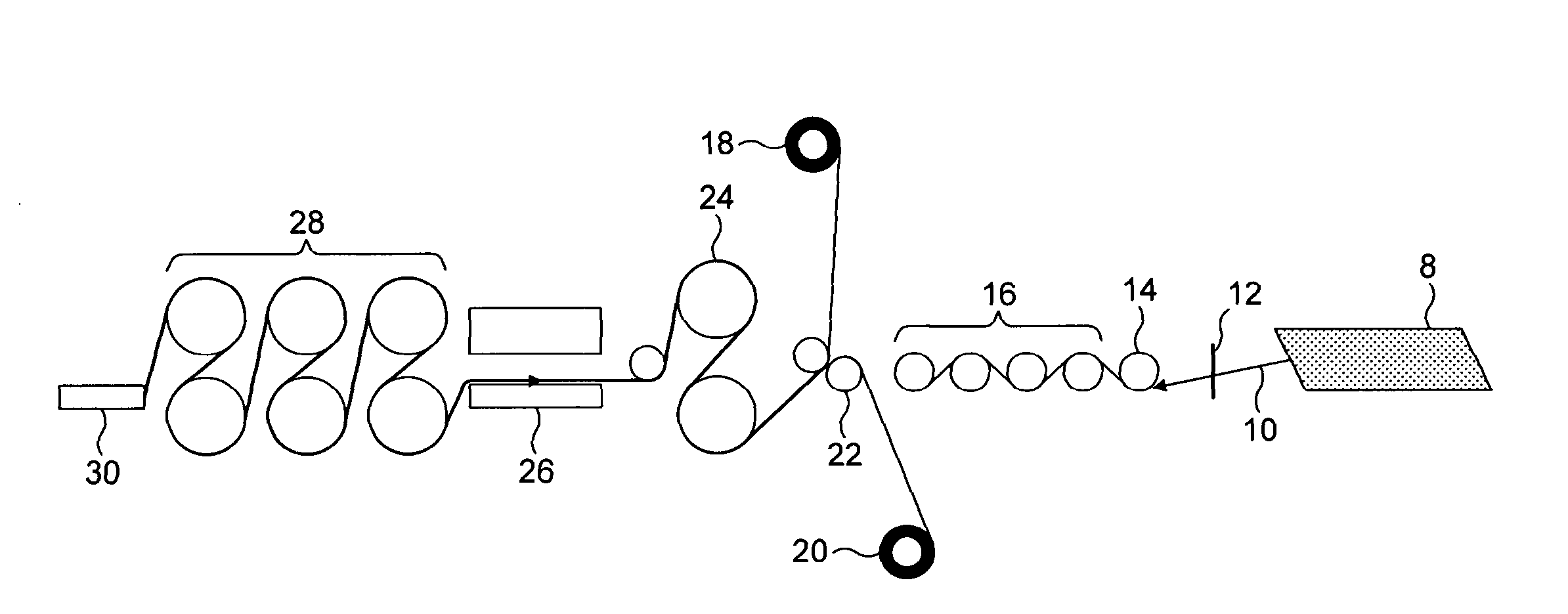
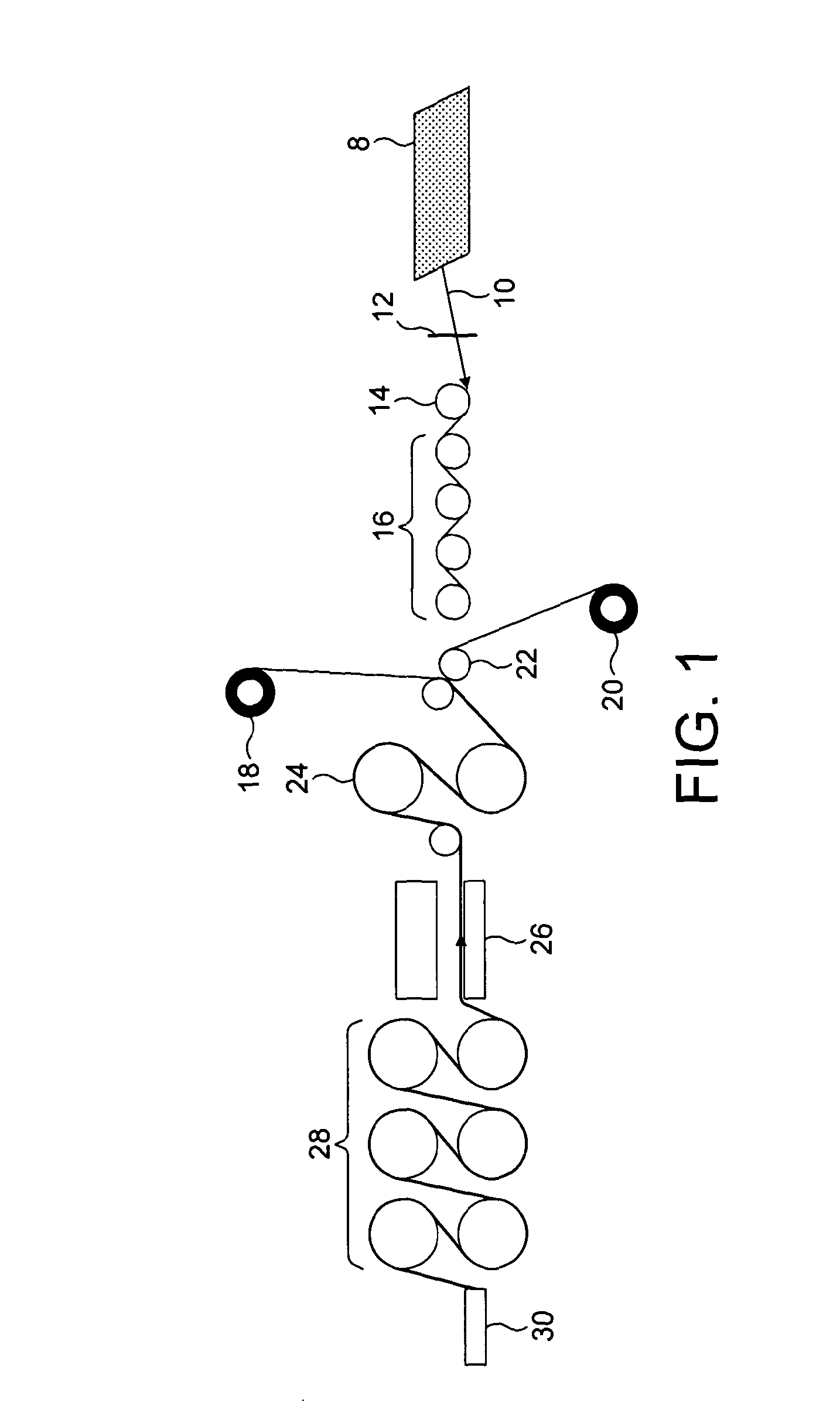
Although the carbon fibres have some electrical conductivity, the presence of the interleaf layers means that this is only predominantly exhibited in the composite in the plane of the laminate.
A lightning strike can cause damage to the composite material which can be quite

Method used


Image

  • Process for manufacturing composite materials
  • Process for manufacturing composite materials
  • Process for manufacturing composite materials

Examples


examples 1 to 6

[0075]In the examples, resin was mixed in a hot-melt process where liquid and powder components were first blended and then mixed again with further powder components that were the curing agent and toughening polyamide 6 particles at nominally 20 microns in diameter, being Orgasol, from Arkema.

[0076]is The curing agent and toughening particles were mixed into the first stage blend with high shear and suitable temperature (80° C.) to allow a “flowable viscosity” for decanting the resin from the mixing vessel without overheating and risking either excessive resin advancement or exothermic reaction. This mixing step can be completed in a batch type process or in a continuous mixing process using for example a twin screw extruder for continuous mixing and feed of hot resin direct to the coating machine.

[0077]In this example when the batch mixing process was complete the fully mixed resin formulation was decanted from the mixing vessel into the coating bath on the reverse roll filming ma...

examples 7 to 8

[0087]The above examples were repeated but this time with different arrangements of impregnation rollers, involving nip rollers which exert a pressure of 36 kg per centimetre width of the conductive fibres and so fall inside the scope of the present invention. The results, together with a variety of mechanical properties widely employed in the art such as Interlaminar Shear Strength, Ultimate Tensile Strength, Open Hole Tension and Compression After Impact, are shown below in Table 2.

TABLE 2ResistanceILSSExampleProcess(Ω)ILSSUDUTSOHTCAI7One stage0.8 659632507692601 × S-wrap3 × nip8One stage1.9365923194801—3 × S-wrapl × nip

examples 9 to 10

[0088]Example 6 was repeated but this time varying the speed of the rollers relative to the speed of the conductive fibres and resin passing over them. Such variation is referred to in the art as “trim” and can be positive (if the rollers are driven faster than the fibres, or negative (if the rollers are driven slower than the fibres).

[0089]The results are presented below in Table 3.

TABLE 3ExampleProcessResistance (Ω)9One stage1.403 × S-wrap, negative trim10One stage1.143 × S-wrap, 1% positivetrim


PUM

PropertyMeasurementUnit
Temperatureaaaaaaaaaa
Fractionaaaaaaaaaa
Linear densityaaaaaaaaaa

Abstract

A process for the manufacture of a prepreg comprising feeding a layer of unidirectional conductive fibres having a defined width, bringing into contact with a first face of the fibres a first layer of resin comprising thermosetting resin, and compressing the resin and fibres together by passing over one or more impregnation rollers, wherein the pressure exerted onto the conductive fibres and resin does not exceed 40 kg per centimetre of the width of the conductive fibres, and the resin being in sufficient amount for the resin to enter the interstices of the fibres and leave a first outer layer of resin essentially free of unidirectional conductive fibres.

Description

TECHNICAL FIELD[0001]The present invention relates to a process for manufacture of prepregs comprising fibres and resin matrix which when stacked to form a laminate and subsequently cured, form composite materials, particularly with improved resistance to damage caused by lightning strikes.BACKGROUND[0002]Composite materials have well-documented advantages over traditional construction materials, particularly in providing excellent mechanical properties at very low material densities. As a result, the use of such materials is becoming increasingly is widespread and their fields of application range from “industrial” and “sports and leisure” to high performance aerospace components.[0003]Prepregs, comprising a fibre arrangement impregnated with resin such as epoxy resin, are widely used in the generation of such composite materials. Typically a number of plies of such prepregs are “laid-up” as desired and the resulting laminate is cured, typically by exposure to elevated temperatures...

Claims


Application Information

Patent Timeline
IPC IPC(8): B32B27/04C09J5/00
CPCB32B5/26C08J5/24B32B27/04B32B5/28Y10T428/249942Y10T428/24994B29C70/38C08J5/243C08J5/249B32B2307/202B32B2305/20B32B2305/30B32B2305/076B32B2379/00B32B2398/10B32B2331/00B32B2367/00B32B2361/00B32B2363/00C08J5/04
Inventor ELLIS, JOHNFISSET, EMILLETILBROOK, DAVIDMACKENZIE, PAULBLANC, ISABELLEFIORE, LUCIENTIZON, BERNADETTE
Owner HEXCEL COMPOSITES SAS
Why Eureka
Try Eureka