Steam power plant with steam turbine unit and process steam consumer, and method for operating a steam power plant with steam turbine unit and process steam consumer

a technology of steam turbine unit and steam power plant, which is applied in the direction of steam use, mechanical equipment, machines/engines, etc., can solve the problems of high steam temperature, high energy consumption of such high-temperature steam, and inability to meet the needs of steam power plant operation, etc., to achieve the effect of reducing the cost improving the overall efficiency of steam power plant, and shortening the piping rou

Inactive Publication Date: 2012-05-10
SIEMENS AG
View PDF5 Cites 10 Cited by
  • Summary
  • Abstract
  • Description
  • Claims
  • Application Information

AI Technical Summary

Benefits of technology

[0010]The invention in this case is based on the idea of achieving a conditioning of a process steam, which is extracted from the steam turbine unit, for the process steam consumer by means of a desuperheater. By means of the desuperheater, it is possible to bring the process steam to a temperature level which is optimized for the process steam consumer. In this case, the desuperheater enables a further use of the energy which is extracted from the process steam. Desuperheaters of this type can be designed as heat exchangers, the desuperheater absorbing energy on the primary side and transferring it to a medium on the secondary side in the process. By using a desuperheater, moreover, other measures for adjustment of the temperature level, such as injecting water or condensate, can theoretically be dispensed with. The invention therefore enables use of the energy which is extracted by means of the desuperheater during simultaneous conditioning of the process steam for the downstream process steam consumer, as a result of which the overall efficiency of the steam power plant is appreciably increased. The invention can also be realized, moreover, with shorter piping routes compared with known interconnections, as a result of which costs for the steam power plant are reduced.
[0011]In an advantageous development of the steam power plant, the steam power plant furthermore comprises a water-steam cycle with a main condensate line and a return condensate line, wherein the desuperheater is connected into the return condensate line on the secondary side. This type of interconnection advantageously enables use of the energy which is drawn from the process steam by means of the desuperheater for preheating a condensate in the water-steam cycle of the steam power plant. As a result of the contribution of the desuperheater for preheating the condensate, a preheater for condensate preheating, which is connected downstream to the desuperheater on the secondary side, is unloaded. As a result, the bled steam from the steam turbine unit which is required for this preheater can be reduced, as a result of which the portion of operating steam in the steam turbine unit is increased. However, as a result of cooling the process steam in the desuperheater, a larger quantity of steam becomes necessary for feeding into the desuperheater in order to be able to provide the same amount of heat, in the form of process steam, for the process steam consumer. Therefore, by using the desuperheater, a shift of the steam quantities especially takes place, but since the bled steam which is at higher pressure, and therefore of higher quality, is reduced, an efficiency enhancement of the steam power plant results from this. By using the condensate as cooling medium for the desuperheater, a costly extraction of main condensate in the water-steam cycle as cooling medium can furthermore be avoided. As a result, the number of interfacing points is reduced and the process-engineering integration is simplified.
[0014]By means of the invention, it is possible to extract the steam which is required for a process steam consumer from a favorable point of the steam turbine unit, and to feed the steam to a process steam consumer in an energetically advantageous manner. A resulting superheated portion of the process steam can be advantageously used at another point of the steam power plant as a result of the desuperheater according to the invention.
[0017]In an advantageous further development, the steam power plant furthermore comprises a water-steam cycle, wherein the heat which is extracted from the superheated steam is fed to the condensate of the water-steam cycle of the steam power plant. As a result, the energy which is drawn from the desuperheater can be used for preheating a condensate in the water-steam cycle of the steam power plant. As a result of the contribution of the desuperheater towards the preheating of the condensate, a preheater for condensate preheating, which is connected downstream to the desuperheater on the secondary side, is unloaded. The necessary bled steam from the steam turbine unit can be reduced for this preheater, as a result of which the portion of operating steam in the steam turbine unit is increased.

Problems solved by technology

At this pressure level, the steam in modern power plants with reheating and high steam temperatures, however, is more highly superheated.
The energy of such highly superheated steam can be used only unsatisfactorily during normal heat transfer in heat exchangers.
For the desorption process, no advantages emerge as a result.
In particular, the energy which lies in the superheating of the steam not being optimally utilized is disadvantageous to this known method.
Also, the extraction of condensate from the water-steam cycle of the power plant for injecting into the highly superheated steam as cooling medium is costly.
Flow losses, which arise because of high-quality process steam, for example highly superheated steam, being extracted from the steam turbine unit, are a general disadvantage to steam power plants with process steam consumers which are known from the prior art, although slightly superheated steam is sufficient for the process steam consumers.

Method used


Image

  • Steam power plant with steam turbine unit and process steam consumer, and method for operating a steam power plant with steam turbine unit and process steam consumer
  • Steam power plant with steam turbine unit and process steam consumer, and method for operating a steam power plant with steam turbine unit and process steam consumer

Examples


Embodiment Construction

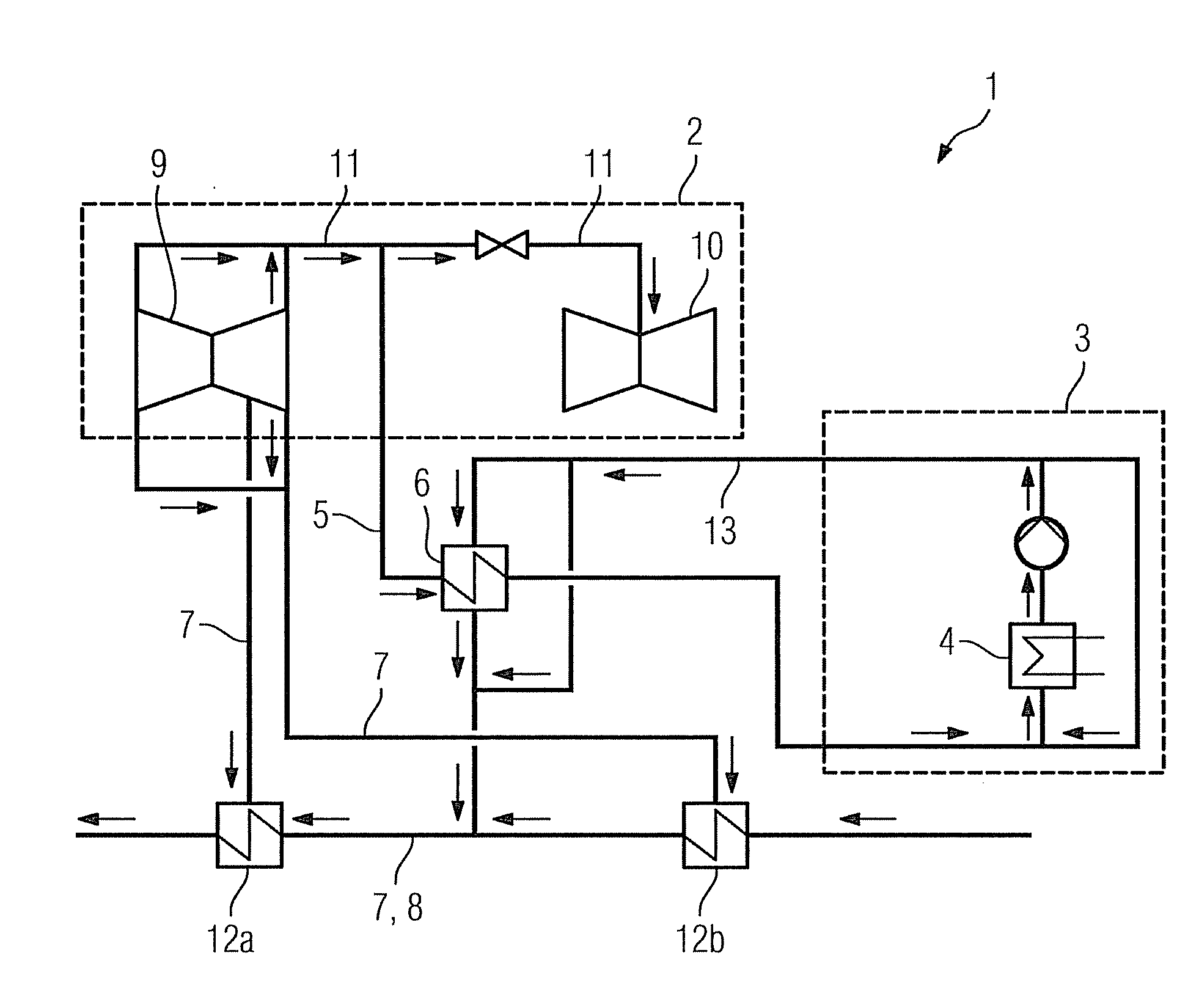
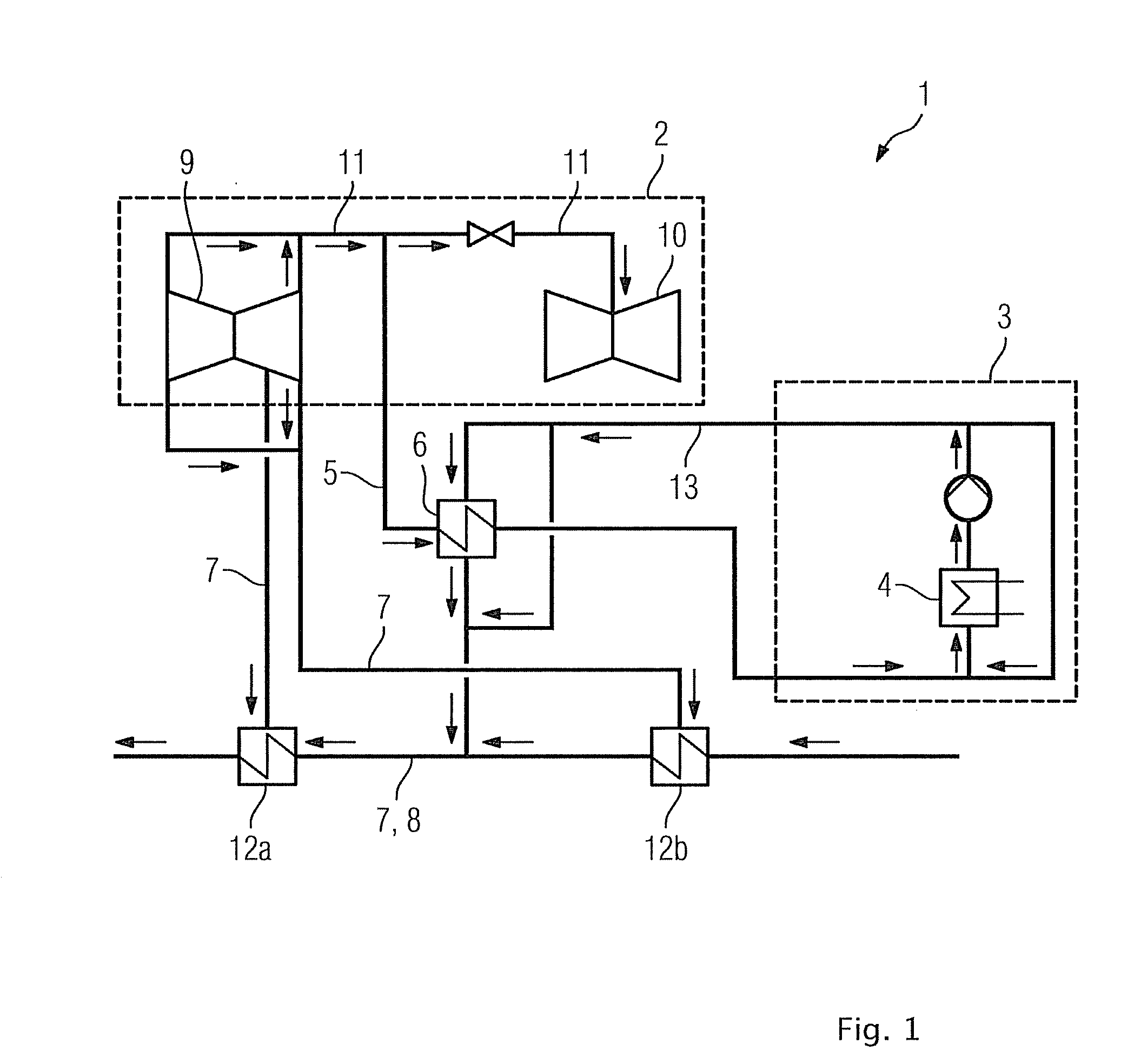
[0021]The steam power plant 1 which is shown in FIG. 1 essentially shows a steam turbine unit 2 and a process steam consumer 3 and also a desuperheater 6.

[0022]The steam turbine unit 2 shows an intermediate-pressure turbine 9 and a low-pressure turbine 10, which are interconnected via a crossover line 11. During operation of the steam power plant 1, superheated steam leaving the intermediate-pressure turbine 9 can therefore be transferred into the low-pressure turbine 10. The bleed line 5 is connected to the crossover line 11. Some of the superheated steam can be branched off from the crossover line 11 through the bleed line 5.

[0023]The bleed line 5 is furthermore connected to the desuperheater 6 on the primary feed side. On the primary discharge side, the desuperheater 6 is connected to the process steam consumer 3. By means of the desuperheater 6, heat is extracted from superheated steam which is guided in the bleed line 5. Slightly superheated steam leaves the desuperheater on th...


PUM


Abstract

A steam power plant having at least one steam turbine unit and a process steam consumer is provided. The process steam consumer includes a heat exchanger. The steam turbine unit is connected to a heat exchanger by means of a extraction steam line, and a desuperheater is connected in the primary side of the extraction steam line, so that process steam extracted through the extraction steam line of the turbine system may be conditioned by the desuperheater to the process conditions of the process steam consumer, and the heat energy removed in the desuperheater can be fed back into the steam power plant system.

Description

CROSS REFERENCE TO RELATED APPLICATIONS[0001]This application is the US National Stage of International Application No. PCT / EP2010 / 058517, filed Jun. 17, 2010 and claims the benefit thereof. The International Application claims the benefits of European Patent Office application No. 09165561. EP filed Jul. 15, 2009. All of the applications are incorporated by reference herein in their entirety.FIELD OF INVENTION[0002]The invention refers to a steam power plant with steam turbine unit and process steam consumer, especially a separator for carbon dioxide as the process steam consumer. The invention also refers to a method for operating a steam power plant with a steam turbine unit and a process steam consumer.BACKGROUND OF INVENTION[0003]Steam power plants (SPP) for generating electric power essentially comprise a steam turbine unit and a fired boiler, or, in the configuration as a gas and steam turbine power plant (CCPP), comprise a gas turbine unit with downstream heat recovery steam...

Claims


Application Information

Patent Timeline
Patent Type & Authority Applications(United States)
IPC IPC(8): F01K17/04F01K17/02F01K7/34
CPCY02E20/14F01K17/02Y02E20/32
Inventor FRÜH, TILMANGRAEBER, CARSTENROST, MIKE
Owner SIEMENS AG
Why Eureka
Try Eureka