Inkjet Printing of Conductive Carbon Nanotubes, Inherently Conductive Polymers, and Metal Particle Inks

a technology of conductive carbon nanotubes and inherently conductive polymers, which is applied in the direction of insulated conductors, non-metal conductors, cables, etc., can solve the problems of insufficient conductive for most uses, high resistance or lower conductivity in the prior art, and high resistance of conductive materials applied by printing

Inactive Publication Date: 2012-05-10
NASA
View PDF16 Cites 40 Cited by
  • Summary
  • Abstract
  • Description
  • Claims
  • Application Information

AI Technical Summary

Benefits of technology

[0017]Another system demonstrated was that composite material comprising a mixture of functionalized CNTs and silver or gold nanoparticles could be applied by inkjet pr...

Problems solved by technology

Although these technologies proved successful for some electronic circuitry applications, the high resistance or lower conductivity in the prior art are not adequate for most uses, including th...

Method used


Image

  • Inkjet Printing of Conductive Carbon Nanotubes, Inherently Conductive Polymers, and Metal Particle Inks
  • Inkjet Printing of Conductive Carbon Nanotubes, Inherently Conductive Polymers, and Metal Particle Inks
  • Inkjet Printing of Conductive Carbon Nanotubes, Inherently Conductive Polymers, and Metal Particle Inks

Examples


example 1

Inkjet Printing of Conductive Ink Containing Carbon Nanotubes.

[0075]The feasibility of printing conductive inks was investigated for integration as the damage detection layer in an in-situ wire damage detection system. Inkjet printing is a common commercial process used in every wire construction. Manufacturers are required by law to print the wire type, gauge, and safety information on the exterior of each foot of manufactured wire. It was hypothesized that this methodology could be used to impart a printed conductive layer onto the wire insulation. To accomplish this, a conductive ink would need to be deposited using a method similar to the commercial wire printing technology.

[0076]The printing method was also examined as a possible means to improving the conductivity of the detection layer. Various commercial off-the-shelf (COTS) printing methods, such as thermal and piezoelectric inkjet printing, screen printing, and bubble jet printing, were examined as different methods for in...

example 2

Printed CNT Electrically Conductive Material Layer as a Dust Screen

Methods:

[0091]Conductive inks were printed onto various substrates as described in Example 1.

Results:

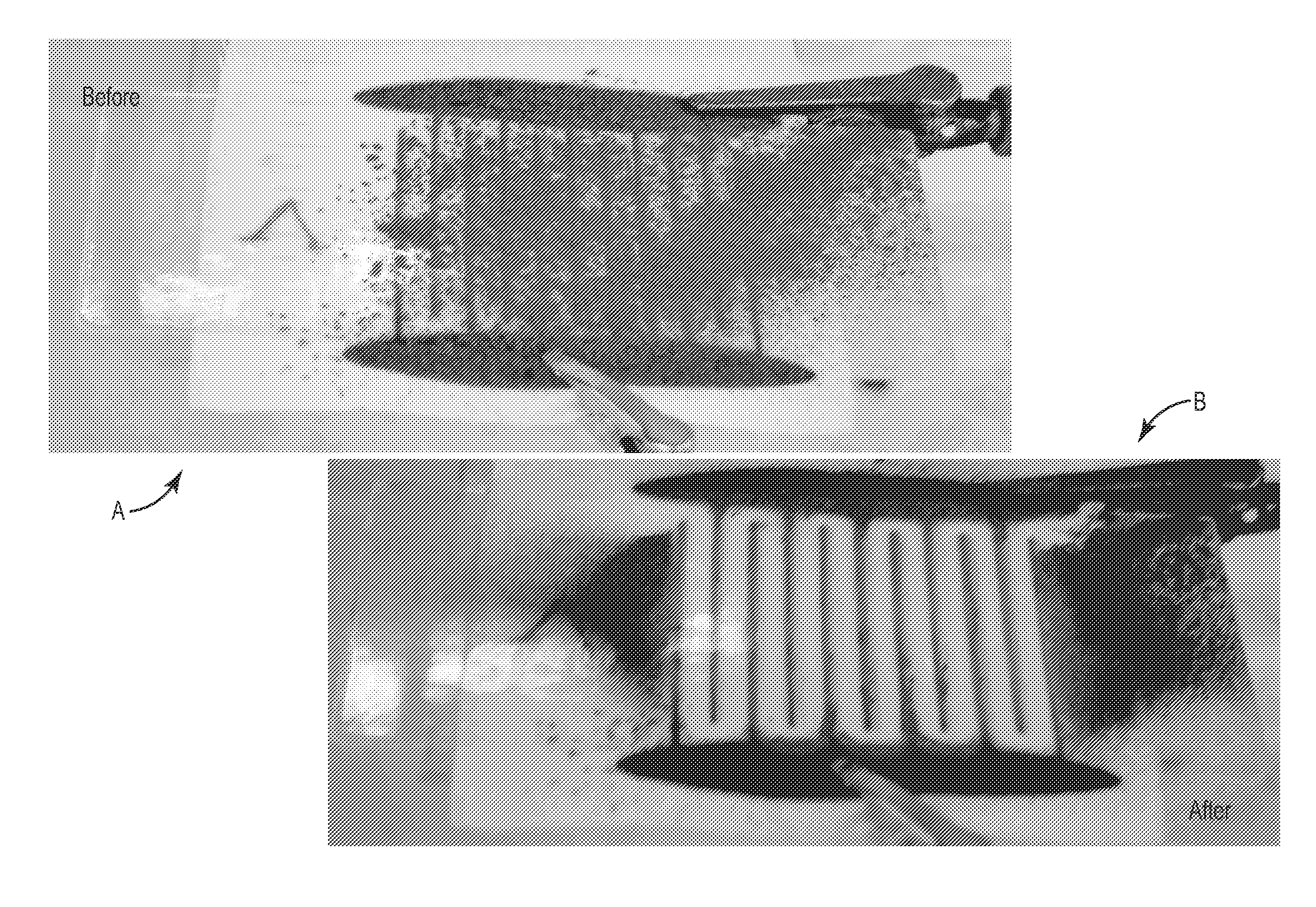
[0092]In FIG. 8 CNT conductive material was applied to a cotton substrate with an inkjet printer in a pattern of lines. The sheet was then laminated with polyethyleneterphthalate (PET) to protect the conductive ink. The dark areas in panel B are the areas with conductive material applied. The white areas did not have conductive ink applied. Dust was applied to the sheet in panel A. A voltage was then applied to the sheets. Panel B shows the same sheet after application of the voltage. Dust was repelled from the entire surface area containing the printed electronics.

[0093]FIG. 9 shows the same result when the CNT conductive material was printed onto a larger cotton substrate with a different conductive pattern.

[0094]FIG. 10 shows the results when the cotton substrate was placed in a vacuum chamber before and after an a...

example 3

Conductive Ink Formulation 1

Ink Formulation

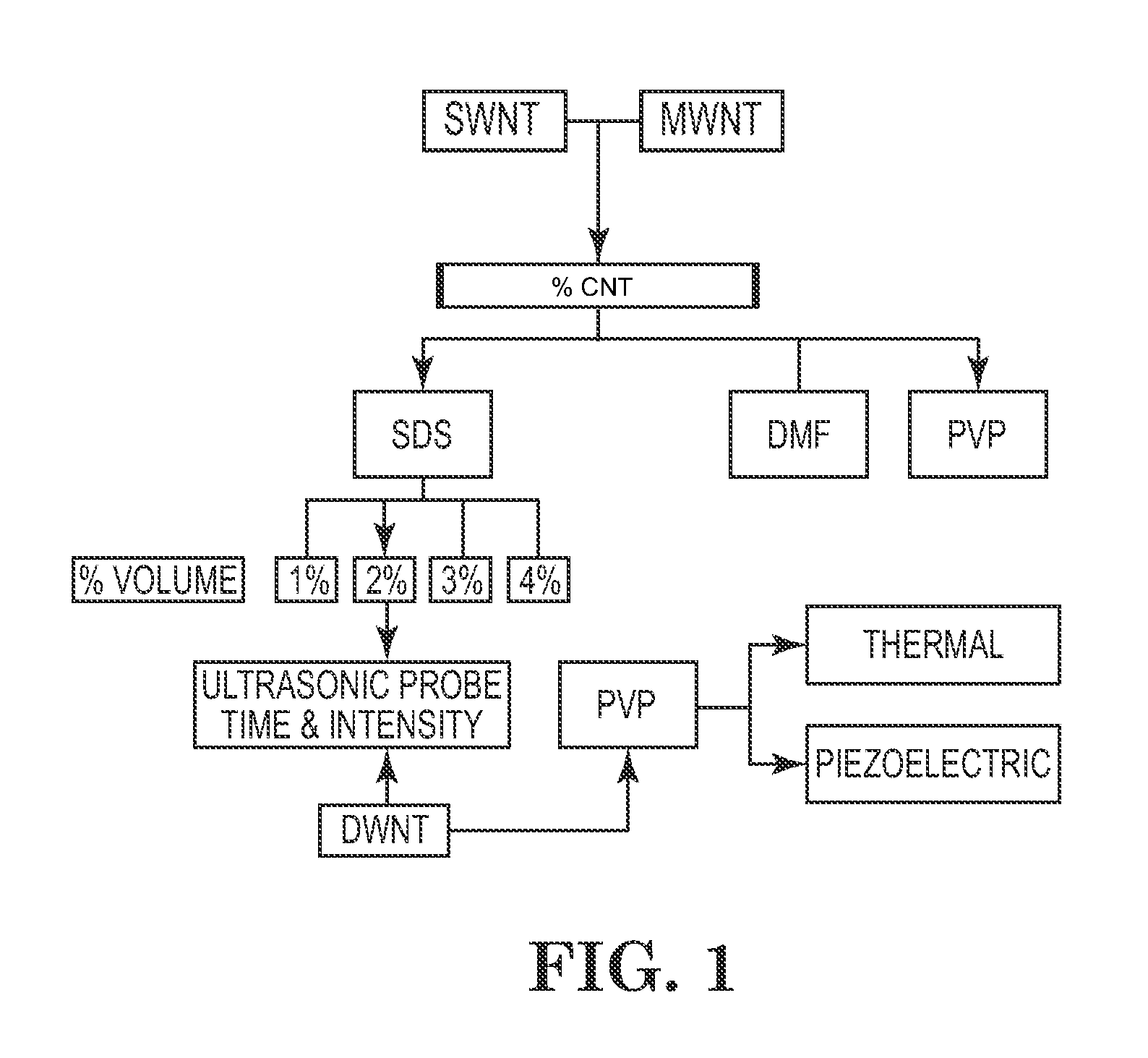
[0095]1.81 g single-wall carbon nanotubes, 0.30 g sodium dodecyl sulfate, and 40.0 g deionized water were placed in a container and the mixture was agitated for 30 seconds by shaking The dark suspension was mixed using a SONICS VCX-750 ultrasonic probe for 60 minutes at 32% amplitude. Care was taken to ensure that only ˜¼ inch of the probe tip was below the surface of the liquid during the sonication process. An additional 2.0 ml of deionized water was added and the dark suspension was mixed using an ultrasonic probe for another 60 minutes (32% amplitude). The suspension was very viscous and difficult to work with. The suspension was transferred to a large container and diluted with several 40.0 ml portions of deionized water to provide a printable conductive ink.

Processing and Evaluation

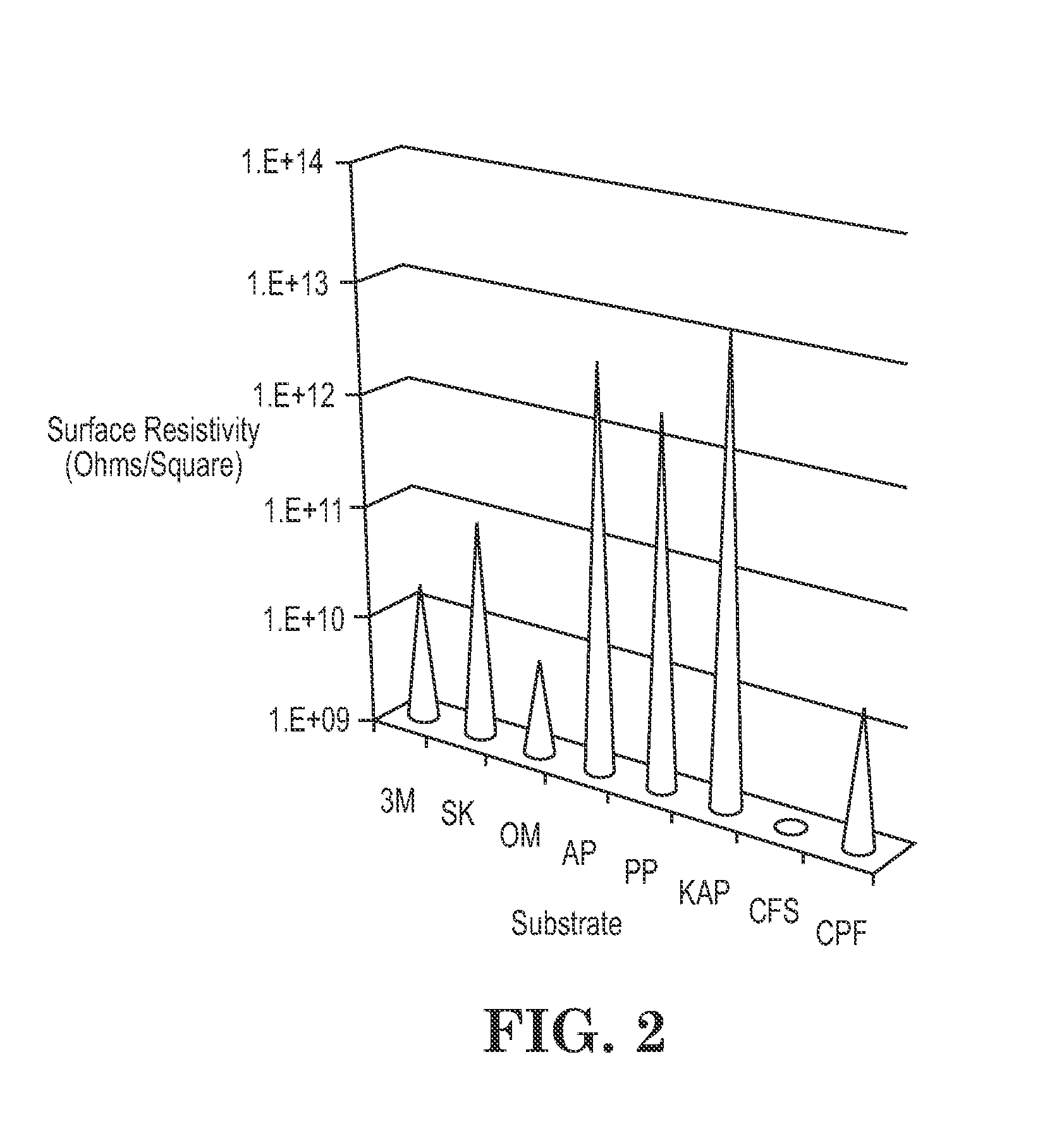
[0096]The printed conductive ink test specimen was allowed to dry at room temperature and humidity (20° C.., 50% R.H.) until no liquid was visible. After d...


PUM

PropertyMeasurementUnit
Temperatureaaaaaaaaaa
Surface resistivityaaaaaaaaaa
Sheet resistanceaaaaaaaaaa

Abstract

Systems and methods for forming conductive materials. The conductive materials can be applied using a printer in single or multiple passes onto a substrate. The conductive materials are composed of electrical conductors such as carbon nanotubes (including functionalized carbon nanotubes and metal-coated carbon nanotubes), grapheme, a polycyclic aromatic hydrocarbon (e.g. pentacene and bisperipentacene), metal nanoparticles, an inherently conductive polymer (ICP), and combinations thereof. Once the conductive materials are applied, the materials are dried and sintered to form adherent conductive materials on the substrate. The adherent conductive materials can be used in applications such as damage detection, particle removal, and smart coating systems.

Description

CROSS-REFERENCE TO RELATED APPLICATIONS[0001]This application claims the benefit under 35 U.S.C. §119(e) of U.S. Provisional Application Ser. No. 61 / 410,467, filed on Nov. 5, 2010, the contents of which are incorporated herein by reference.ORIGIN OF INVENTION[0002]The invention described herein was made in the performance of work under a NASA contract and by employees of the United States Government and is subject to the provisions of Public Law 96-517 (35 U.S.C. §202) and may be manufactured and used by or for the Government for governmental purposes without the payment of any royalties thereon or therefore. In accordance with 35 U.S.C. §202, the contractor elected not to retain title.BACKGROUND OF THE INVENTION[0003]Inkjet printing is a common commercial process. In addition to the familiar use in printing documents from computers, it is used in some industrial applications. Wire manufacturers are required by law to print the wire type, gauge, and safety information on the exterio...

Claims


Application Information

Patent Timeline
IPC IPC(8): H01B7/18H01B1/02B05D5/12B05D3/00H01B1/04H01B1/12B82Y30/00B82Y40/00
CPCB41M3/006B41M5/0023H01B1/04H01B1/02B82Y30/00B05D1/26B05D5/12C23C18/1262C23C18/18C23C18/31
Inventor ROBERSON, LUKE B.WILLIAMS, MARTHA K.GIBSON, TRACY L.TATE, LANETRA C.SNYDER, SARAH J.FORTIER, CRAIG R.
Owner NASA
Why Eureka
Try Eureka