

Spiral wound reverse osmosis membrane element
- Summary
- Abstract
- Description
- Claims
- Application Information
AI Technical Summary
Benefits of technology
Problems solved by technology
Method used
Image

Examples
embodiment 1
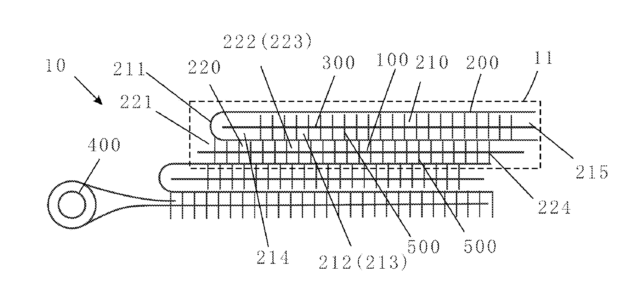
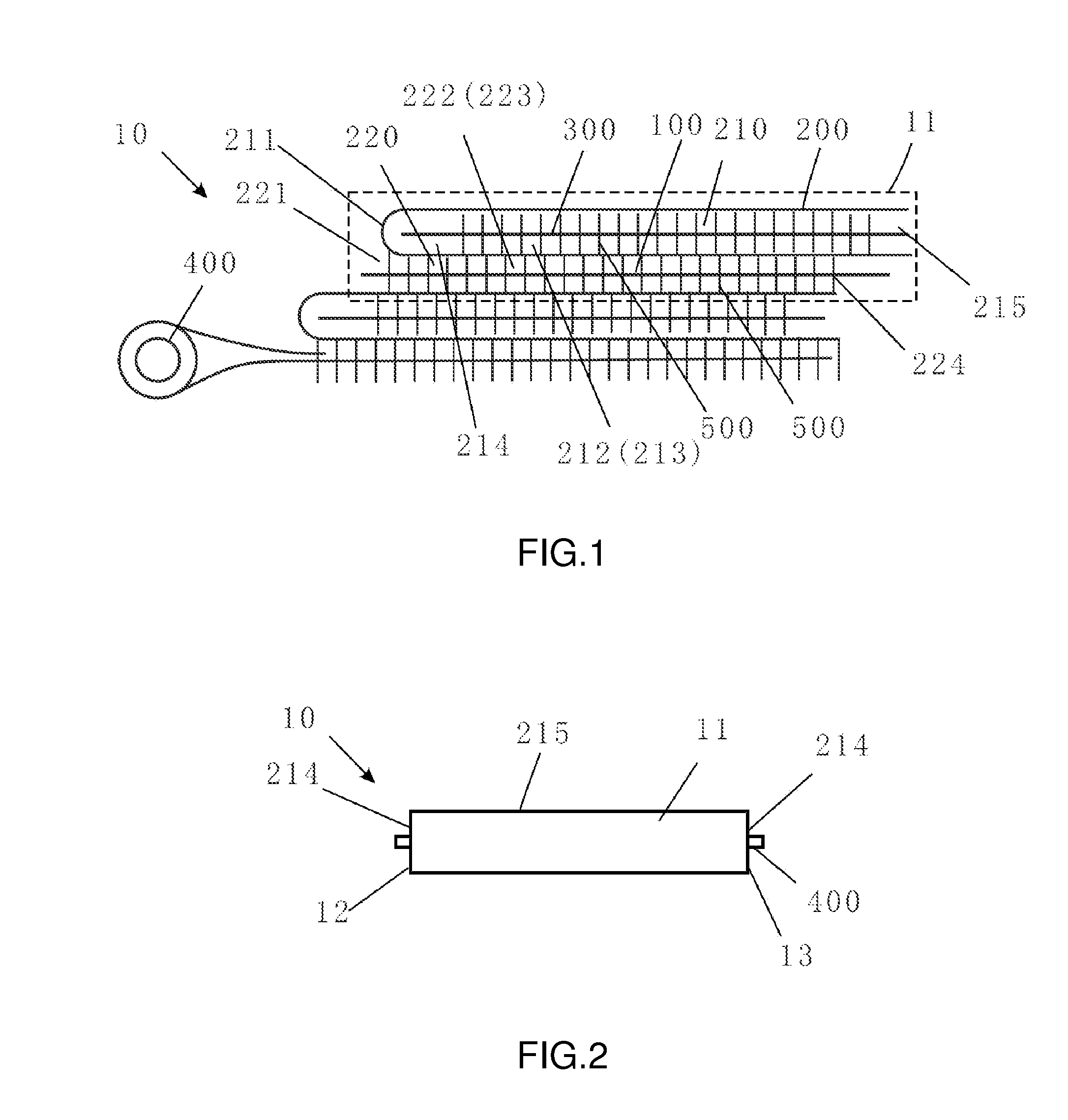
[0019]As illustrated in FIG. 1, the spiral wound reverse osmosis membrane element 10 of the present embodiment is formed by winding two sets of water purification membrane modules 11 (in the present embodiment there are two sets) around a central treated water pipe 400, and each set of the water purification membrane module 11 is formed by laminating a mesh-like treated water flow guiding member 100, a reverse osmosis membrane 200 and a mesh-like feed water flow guiding member 300.
[0020]The reverse osmosis membrane 200 is folded to form a feed water flow channel 210 therein along its inner surface. A treated water flow channel 220 is formed between outer surfaces of adjacent membranes (the bottom outer surface of the reverse osmosis membrane of the water purification membrane module at the bottom and the upper outer surface of the reverse osmosis membrane of the water purification membrane module at the top also form treated water flow channels after winding). The mesh-like feed wat...
embodiment 2
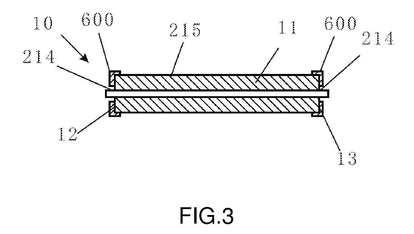
[0024]As illustrated in FIG. 3, the present embodiment differs from Embodiment 1 in that the feed water flow channel 210 is closed and sealed at areas remote from the central treated water tube 400 at two sides 212, 213 adjacent to the folded side 211 in a different manner. In the present embodiment, annular end covers 600 (coated with glue inside) block the outer area of the two end surfaces 12, 13 of the spiral wound reverse osmosis membrane element after the water purification membrane modules 11 are wound around the central treated water tube 400, and a gap is provided between the central treated water tube 400 and each of the end covers 600 to form raw water inlets 214. Other structures of the present embodiment are similar to those of Embodiment 1. The manner of sealing in the present embodiment is advantageous in that it is easier to assemble the membrane element.
embodiment 3
[0025]As illustrated in FIG. 4, the present embodiment is different from Embodiments 1 and 2 in that feed water tubes 800 are provided inside the raw water inlets 214 to eliminate dead angles of the raw water inlets and to prevent the raw water inlets from clogging and thereby affecting water quality. The feed water tube 800 extends from the raw water inlet 214 at one end of the membrane element to the raw water inlet 214 at the other end of the member element, and the feed water tube 800 is provided with a plurality of through-holes (not shown in the figures) which open towards the concentrate outlets 215.
[0026]With the aforementioned improvements, the feed water first enters the feed water tubes 800, and then the feed water sprays into the feed water flow channels 300 from the through-holes of the feed water tubes 800 towards the direction of the concentrate outlets 215. In this way, feed water is entered in an even manner and feed water dead angle could be eliminated, thereby pre...
PUM
| Property | Measurement | Unit |
|---|---|---|
| Length | aaaaa | aaaaa |
Abstract
Description
Claims
Application Information