Novel Multi-Point Scan Architecture

a scanning architecture and multi-point technology, applied in the field of optical scanning instruments, can solve the problems of limiting the practical imaging depth of in vivo imaging applications, performance degradation, etc., and achieve the effects of improving depth imaging, high frame rate, and rapid switching

Active Publication Date: 2012-05-10
THE ARIZONA BOARD OF REGENTS ON BEHALF OF THE UNIV OF ARIZONA
View PDF6 Cites 60 Cited by
  • Summary
  • Abstract
  • Description
  • Claims
  • Application Information

AI Technical Summary

Benefits of technology

[0011]The above embodiments use a multi-point scanning geometry. This design maintains the high frame rate of the slit-scan system and still allows rapid switching between grayscale and multi-spectral imaging. In a confocal configuration, the multi-point scanning system's confocal performance is close to that of a single point scan system and is expected to yield improved depth imaging when compared to a slit-scan system.

Problems solved by technology

Recent Monte Carlo simulation results show that performance degrades with depth for both point-scan and slit-scan systems, but that in the slit-scanning geometry the effects are severe enough to limit the practical imaging depth for in vivo imaging applications.

Method used


Image

  • Novel Multi-Point Scan Architecture
  • Novel Multi-Point Scan Architecture
  • Novel Multi-Point Scan Architecture

Examples


first embodiment

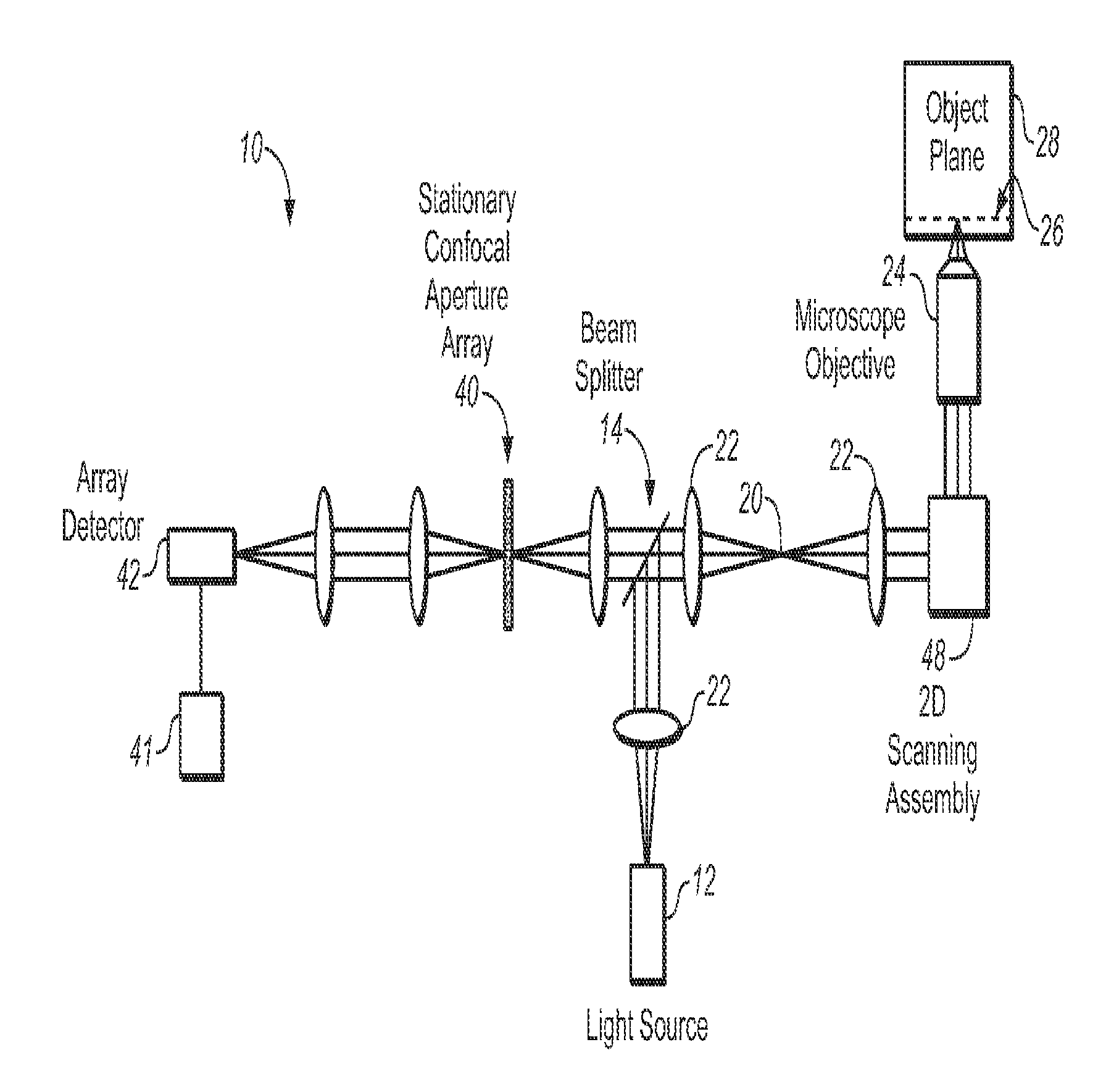
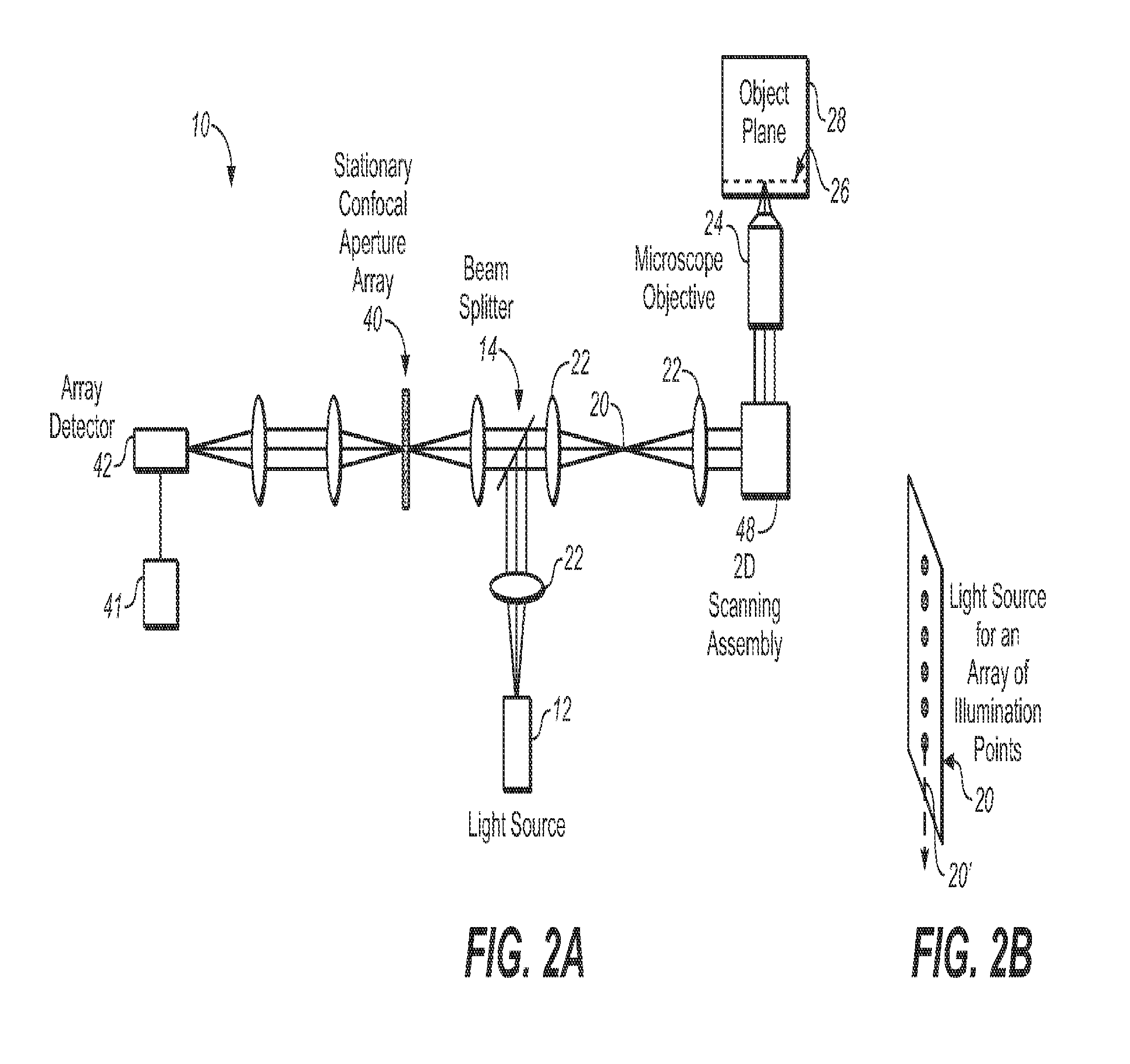
[0026]FIG. 2A is a schematic view of a multi-point scanning system employing a stationary confocal aperture array to illustrate the invention. The system 10 utilizes a light source 12 and a beamsplitter 14, to couple excitation light into the system. The light source 12 provides a substantially one dimensional array 20 of two or more illumination beams spread along a first dimension. In this application, the phrase “along a first dimension” means along a first line or direction, and the phrase “along a second dimension” means along a second line or direction.

[0027]The array 20 of illumination beams is shown schematically in FIG. 2B as an array of illumination points, where the first dimension is along line or direction 20′. The light source 12 may include a laser or lamp (not shown), a cylindrical lens (not shown), and a grating or pinhole aperture array (not shown) for generating a substantially one dimensional array 20 of two or more illumination beams spread along a first dimensi...

second embodiment

[0031]FIG. 3A is a schematic view of a multi-point scanning system 100 employing a moving confocal aperture array to illustrate the invention. The system 100 differs from system 10 of FIG. 2A in that the light source 112 generates a substantially one dimensional array 120 of two or more illumination beams spread along a first dimension 120′ shown in FIG. 3B, where the array 120 is scanned also substantially along the first dimension 120′. Hence instead of using a 2D scanning assembly as in system 10, a scan mirror 152 scanning in a second direction or dimension transverse to the dimension 120′ (such as about an axis that is perpendicular to the page) is adequate to accomplish the 2D image scanning in the manner illustrated in FIG. 1E. The generation of a scanning array of two or more illumination beams spread along a first dimension 120′ and also scanning along first dimension 120′ is described below in reference to FIGS. 5A-5D.

[0032]In FIG. 3A, the light from array 120 is conveyed ...


PUM


Abstract

The embodiments of this invention use a multi-point scanning geometry. This design maintains the high frame rate of the slit-scan system and still allows both grayscale and multi-spectral imaging. In a confocal configuration, the multi-point scanning system's confocal performance is close to that of a single point scan system and is expected to yield improved depth imaging when compared to a slit-scan system, faster imaging than a point scan system, and the capability for multi-spectral imaging not readily achievable in a Nipkow disk based confocal system.

Description

BACKGROUND[0001]This invention relates in general to an optical scanning instrument, and more particularly to a multi-point scan architecture.[0002]Confocal microendoscopy is an emerging technology that allows in situ confocal microscopic imaging of cells in live animals and humans. A number of approaches to confocal microendoscopy have been developed. The two most common methods are those that employ a coherent fiber optic bundle to relay the image plane of confocal microscope into the body, and those that build a miniaturized confocal microscope with the scanning mechanism into the distal tip of the flexible imaging device.[0003]For the miniaturized confocal microscope method, see Dickensheets, D. L., et al., “Micromachined scanning confocal optical microscope,”Optics Letters 21, 764-766 (1996), Kiesslich R, et al., “Confocal laser endoscopy for diagnosing intraepithelial neoplasias and colorectal cancer in vivo,”Gastroenterology 127, 706-713 (2004). For the coherent fiber optic b...

Claims


Application Information

Patent Timeline
Patent Type & Authority Applications(United States)
IPC IPC(8): G02B21/06G01J1/58
CPCG02B21/0028G02B21/0032G02B21/0076G02B21/0044G02B21/004
Inventor GMITRO, ARTHUR F.ROUSE, ANDREW R.TANBAKUCHI, ANTHONY A.
Owner THE ARIZONA BOARD OF REGENTS ON BEHALF OF THE UNIV OF ARIZONA
Why Eureka
Try Eureka