Method for manufacturing a thermally-assisted magnetic head

Active Publication Date: 2012-05-17
TDK CORPARATION
View PDF6 Cites 10 Cited by
  • Summary
  • Abstract
  • Description
  • Claims
  • Application Information

AI Technical Summary

Benefits of technology

[0018]The object of the invention is to provide a method for manufacturing a thermally-assisted magnetic head that efficiently heats a magnetic recording medium by appropriately aligning a core of a waveguide in a slider and a laser diode (LD), the waveguide guiding light to an air bearing surface, and the LD generating the light that is to enter the core.

Problems solved by technology

As a result, it becomes difficult to record information using a conventional magnetic recording head.
The conventional magnetic recording head has such a drawback, and this is a large obstacle to achieving an increase in the recording density.
Ordinary light cannot be tapered to a smaller region than its wavelength due to diffraction limitations.
Direct irradiation of light generates the near-field light in the plasmon antenna; however, a conversion efficiency of converting irradiated light into the near-field light is low with this method.
Then, the distance between an edge part of the MR element on the ABS and the magnetic recording medium increases, causing a problem that servo signals recorded on the magnetic recording medium cannot be read during the recording process.
Moreover, when the heat generation is large, the plasmon antenna may melt.
When a positional gap between the LD and the core is present, energy loss occurs, causing unnecessary heat generation.
As a result, the heat may cause alterations and / or deformations on each part of the slider.
Also, since it is necessary for high energy laser light to enter into the core in view of the fact that the loss may occur, the LD needs to generate the high energy laser light, which in turn causes negative effects, such as a short lifetime.
However, since laser light irradiated from the LD of the LD unit is not actually checked, sufficient positional accuracy may not be obtained.
However, even if the alignment of the slider and the LD unit is performed according to this method, heat application efficiency of a magnetic recording medium may not be sufficient at the time of the thermally-assisted magnetic recording.

Method used


Image

  • Method for manufacturing a thermally-assisted magnetic head
  • Method for manufacturing a thermally-assisted magnetic head
  • Method for manufacturing a thermally-assisted magnetic head

Examples


Embodiment Construction

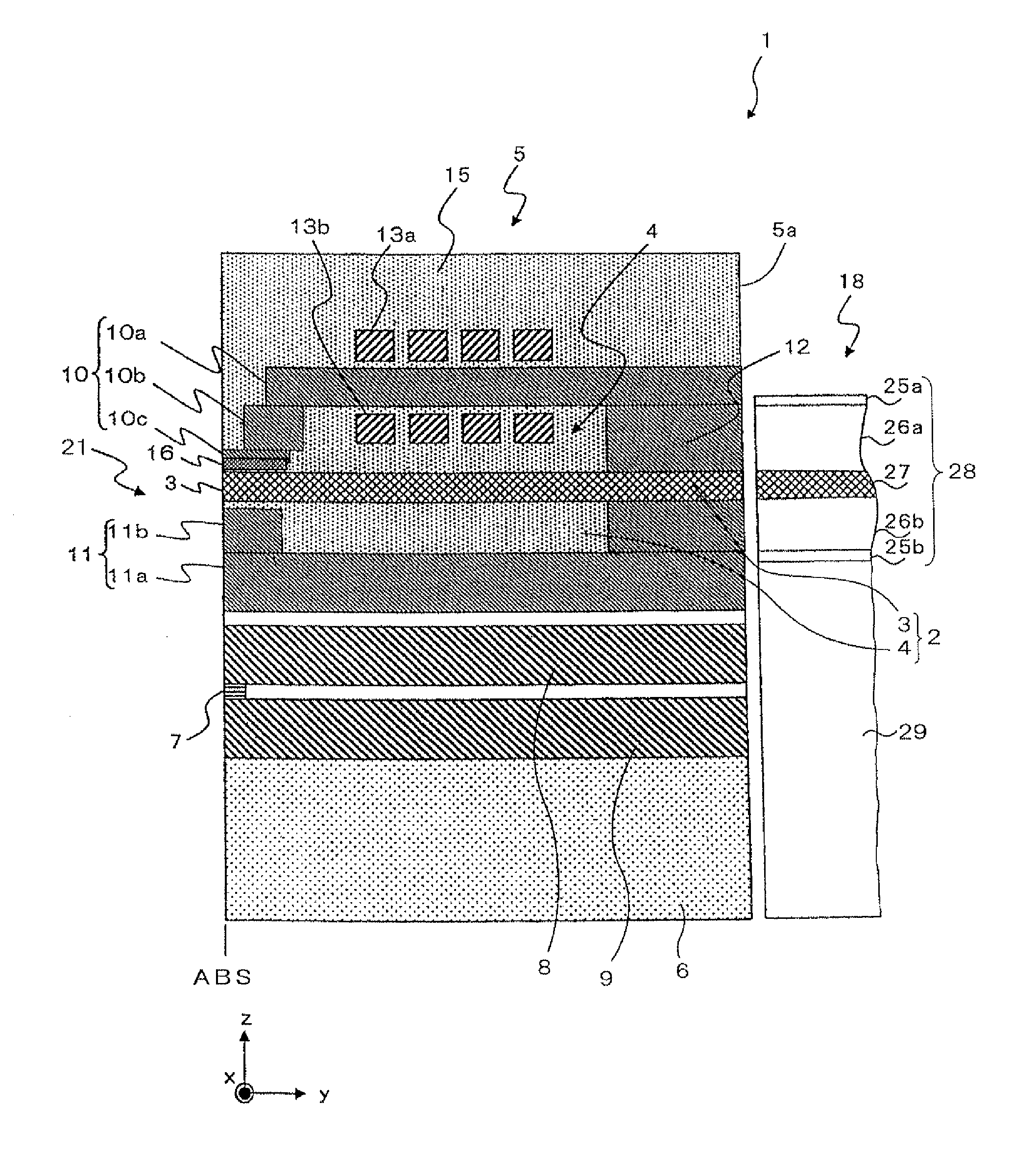
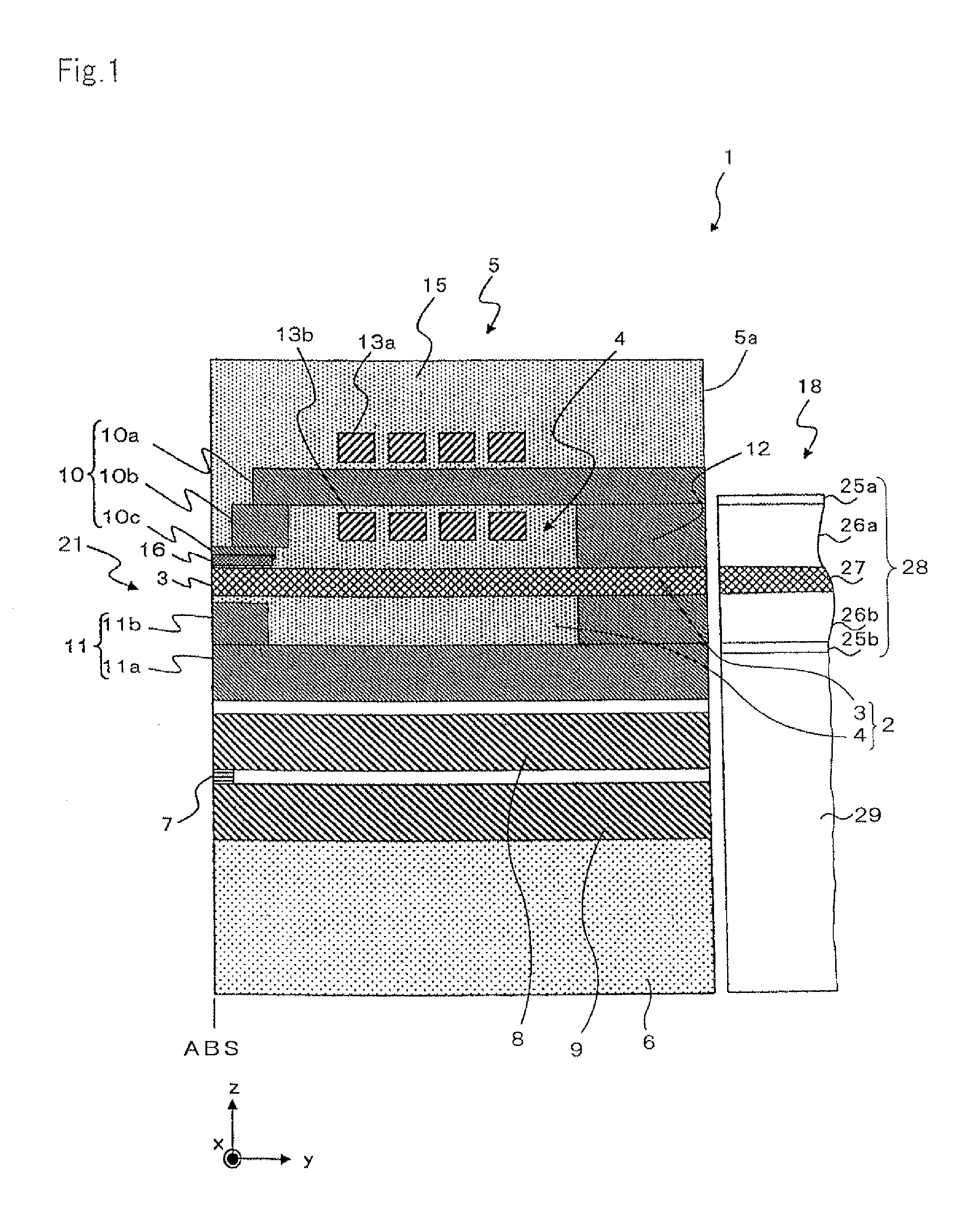
[0038]A thermally-assisted magnetic head of the present invention will be described referring to the figures. Initially, a basic configuration of a thermally-assisted magnetic head 1 of the present invention will be described. The thermally-assisted magnetic head 1 performs a so-called thermally-assisted magnetic recording, which records information by applying a magnetic field when coercive force is partially decreased by heating the magnetic recording medium.

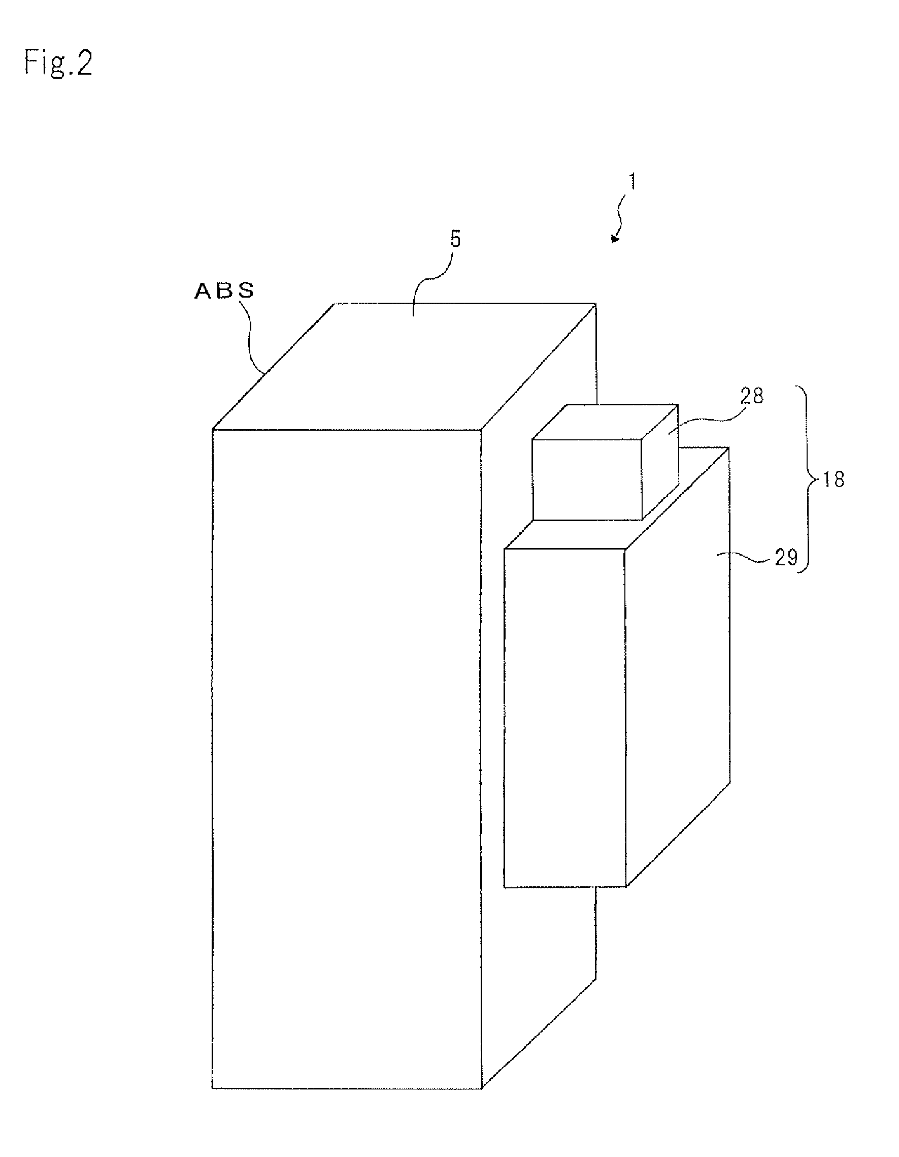
As illustrated in FIGS. 1 and 2, the thermally-assisted magnetic head 1 is configured with a slider 5 and a laser diode (LD) unit 18. The slider 5 includes an MR element 7 that configures a reproducing head part, a magnetic recording element 21 that configures a recording head part, and a waveguide 2 into which laser light utilized to heat the magnetic recording medium enters. The waveguide 2 is configured with a core 3 and a cladding 4 that surrounds the vicinity of the core 3. The LD unit 18 includes an LD 28 that is a light...


PUM

PropertyMeasurementUnit
Strengthaaaaaaaaaa

Abstract

In a method for manufacturing a thermally-assisted magnetic head that includes a slider and an LD unit, the slider including an air bearing surface (ABS) that faces a recording medium and including a waveguide with a core for light propagation that extends from a light entering surface, which is different from the ABS, to the ABS, the LD unit being attached to the light entering surface of the slider, and the thermally-assisted magnetic head performing magnetic recording while heating the recording medium with near-field light that is excited from linearly polarized laser light, the LD unit is disposed in a position facing the light entering surface of the slider, a photo detector is disposed in a position facing the ABS of the slider, and a polarizer transmitting only light having a polarization component that is orthogonal to a polarization direction of the linearly polarized laser light is disposed between the ABS and the photo detector. An LD of the LD unit is activated, and the linearly polarized laser light is enabled to enter into the core from the light entering surface of the slider. Light radiated from the ABS is enabled to enter into the polarizer, and an alignment of the slider and the LD unit is performed while the photo detector detects light that is transmitted through the polarizer.

Description

BACKGROUND OF THE INVENTION[0001]1. Field of the Invention[0002]The present invention relates to a method for manufacturing a thermally-assisted magnetic head, which irradiates near-field light to a magnetic recording medium, reduces coercive force of the magnetic recording medium, and records information.[0003]2. Description of the Related Art[0004]In recent years, for magnetic recording devices such as magnetic disk devices, etc., performance improvements of a magnetic head and a magnetic recording medium are demanded in association with high recording density. As the magnetic head, a composite-type magnetic head, in which a reproducing head that has a magneto resistive effect element (MR element) for reading and a magnetic recording head that has an inductive-type electromagnetic transducer element (a magnetic recording element) for writing are laminated on a substrate, has widely been utilized. In the magnetic disk devices, the magnetic head flies slightly above a surface of the...

Claims


Application Information

Patent Timeline
IPC IPC(8): G11B5/127
CPCG02B6/4202G11B5/105G11B5/3116G11B5/314G11B5/6088G11B2005/0021Y10T29/49052Y10T29/49043Y10T29/49048Y10T29/49044Y10T29/49032Y10T29/49046Y10T29/49041
Inventor HARA, SHINJISHIMAZAWA, KOJIKOMURA, EIJICHOU, TSUTOMUTAKAYAMA, SEIICHI
Owner TDK CORPARATION
Why Eureka
Try Eureka