Hall effect plasma thruster

a plasma thruster and hall effect technology, applied in the field can solve the problems of increasing the required plasma ejection speed, unable to solve the loss of efficiency associated, and unable to provide conventional ceramics based on boron nitride, so as to increase the lifetime of hall effect plasma thrusters and achieve high energy efficiency.

Active Publication Date: 2012-05-17
INST OF FUNDAMENTAL TECHNOLOGICAL RES POLISH ACAD OF SCI +3
View PDF1 Cites 16 Cited by
  • Summary
  • Abstract
  • Description
  • Claims
  • Application Information

AI Technical Summary

Benefits of technology

[0009]An object of the present invention is to remedy the above-mentioned drawbacks and in particular to increase the lifetime of Hall effect plasma thrusters while maintaining a high level of energy efficiency.

Problems solved by technology

The lengthening of missions for telecommunications satellites and the increase in the required plasma ejection speed (in particular for so-called high specific impulse thrusters) require ever-longer lifetimes, which can no longer be provided by conventional ceramics based on boron nitride.
Those studies reveal the advantage of graphite in terms of lifetime, but make no attempt at solving the problem of the loss in efficiency associated with the plasma being short-circuited.
Boron nitride-based ceramics enable Hall effect thrusters to achieve performance levels that are high in terms of efficiency, but they present high rates of erosion under ion bombardment that limit the lifetime of such thrusters to about 10,000 hours (h) and that also limit their operation at the highest specific impulses.

Method used


Image

  • Hall effect plasma thruster
  • Hall effect plasma thruster
  • Hall effect plasma thruster

Examples


Embodiment Construction

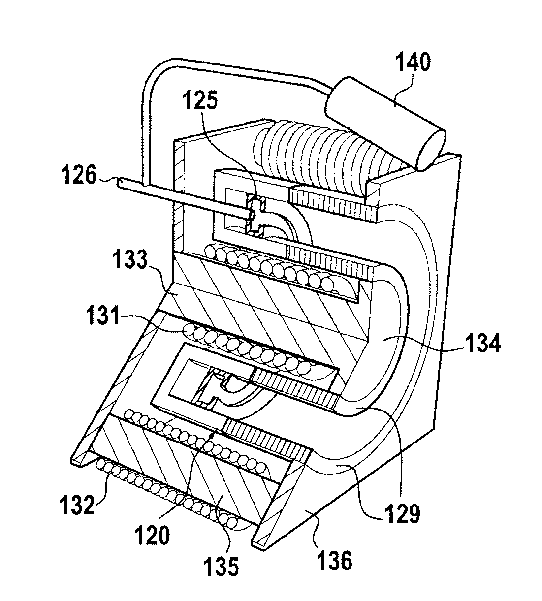
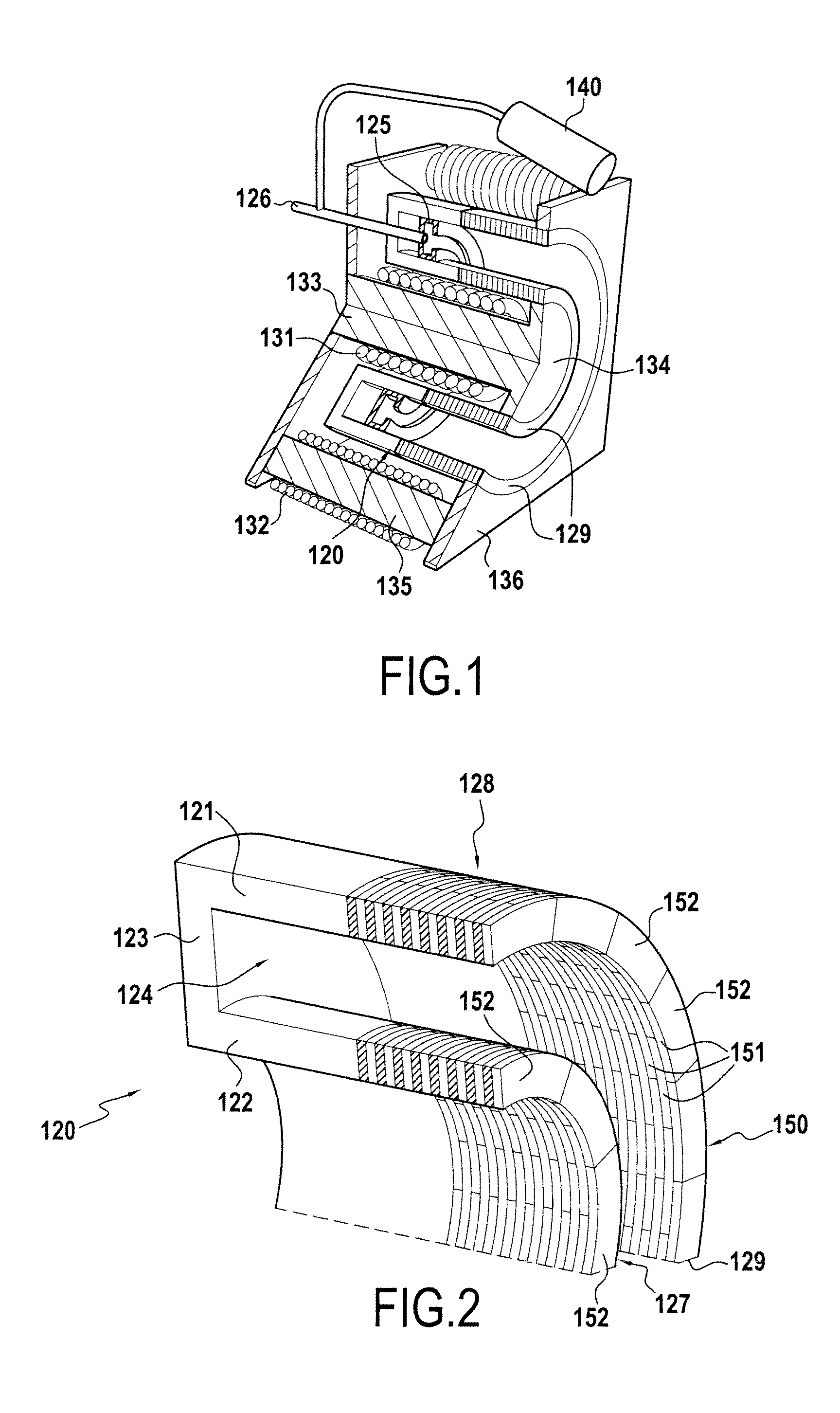
[0033]FIG. 1 shows an example of a Hall effect plasma thruster, also known as a stationary plasma thruster (SPT), to which the invention is applicable and that can be used in particular for electric propulsion of satellites.

[0034]A Hall effect thruster of this type comprises the following main elements:[0035]a discharge channel or main annular channel 120 for ionizing and acceleration;[0036]an annular anode 125 concentric with the main annular channel 120;[0037]a pipe 126 and a manifold associated with the anode 125 and with the main annular channel 120 to feed it with an ionizable gas such as xenon;[0038]a hollow cathode 140; and[0039]a magnetic circuit 131 to 136 for creating a magnetic field in the main annular channel.

[0040]The anode 125 and the manifold for ionizable gas serves to inject the propellant (such as xenon) into the thruster and to collect the electrons of the plasma discharge.

[0041]The hollow cathode 140 serves to generate electrons that are used for creating a plas...


PUM


Abstract

The Hall effect plasma thruster comprises a main annular channel (120) for ionization and acceleration that presents an open downstream end (129), at least one cathode, an annular anode concentric with the main annular channel (120), a pipe and a manifold for feeding the channel (120) with ionizable gas, and a magnetic circuit for creating a magnetic field in said main annular channel (120). The main annular channel (120) comprises inner and outer annular wall portions (127,128) situated in the vicinity of said open end (129), each of which comprises an assembly of juxtaposed conductive or semi-conductive rings (150) in the form of laminations separated by fine layers of insulation (152).

Description

FIELD OF THE INVENTION[0001]The present invention provides a Hall effect plasma thruster having a main annular channel for ionization and acceleration that presents an open downstream end, at least one cathode, an annular anode concentric with the main annular channel, a pipe and a manifold for feeding the channel with ionizable gas, and a magnetic circuit for creating a magnetic field in said main annular channel.[0002]In particular, the invention provides Hall effect plasma thrusters used for electric propulsion of satellites.PRIOR ART[0003]The lifetime of Hall effect plasma thrusters is determined essentially by the erosion of the ceramic insulating channel under the effect of ion bombardment. Because of the topography of electric potential in the channel, some of the ions that are created are accelerated radially towards the walls.[0004]The lengthening of missions for telecommunications satellites and the increase in the required plasma ejection speed (in particular for so-calle...

Claims


Application Information

Patent Timeline
Patent Type & Authority Applications(United States)
IPC IPC(8): F03H1/00
CPCF03H1/0075F03H1/0062H01J27/143H05H1/54
Inventor BARRAL, SERGEZURBACH, STEPHAN J.
Owner INST OF FUNDAMENTAL TECHNOLOGICAL RES POLISH ACAD OF SCI
Why Eureka
Try Eureka