Microelectrode and multiple microelectrodes

Active Publication Date: 2012-05-17
NEURONANO AB
View PDF2 Cites 34 Cited by
  • Summary
  • Abstract
  • Description
  • Claims
  • Application Information

AI Technical Summary

Benefits of technology

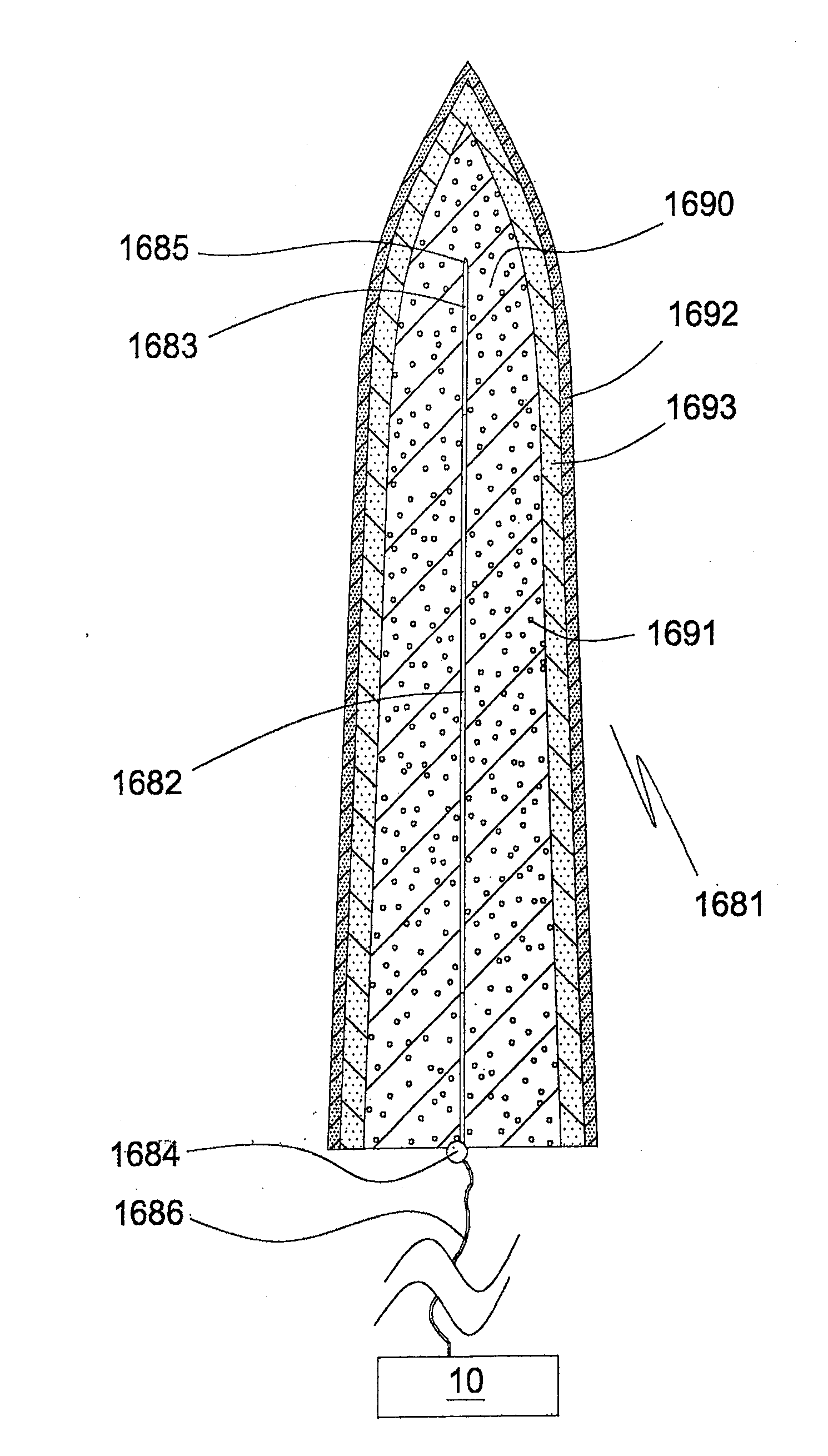
[0107]A method of inserting or implanting a flexible medical microelectrode of the invention in tissue in a desired configuration comprises: providing the electrode in the desired configuration at least partially embedded in a substantially rigid biocompatible water soluble or biodegradable matrix comprising a drug capable of release into a body fluid; inserting or implanting the matrix embedded electrode into tissue; allowing the matrix to dissolve or to be degraded in situ. It is preferred for the matrix to comprise a proximal section of lower dissolution or degradation rate and a distal section of higher dissolution or degradation rate.
[0108]A method of inserting or implanting a

Problems solved by technology

However, little attention has been paid to the injuries and complications caused by the implantation procedure.
Not only can these consequences lead to an impaired function of the implant, they may also harm the individual in which the electrodes are implanted.
1) When implanting microelectrodes in central nervous tissue there is, besides the general risk of open surgery, local risks such as bleedings and also infarctions of the tissue. Electrodes may punctuate blood vessels during implantation. This may cause bleeding and vasoconstriction. A strong inflammatory response to blood cells and proteins that leaked into the neural tissue can be thus triggered and might affect the tissue over extended periods of time. This may in turn induce cell death in the area supplied by the affected vessel. As a consequence the function of the electrode implant can be impaired.
2) General surgery and particular implantation of artificial devices also increase the risk of infections. The surgical area may be infected at the time of surgery or within the early recovery phase after surgery. The presence of a foreign body material (the implant itself) can also function as a locus minoris for establishing an infection in the tissue surrounding the electrodes. Tissue infections around implants are in general more difficult to treat with antibiotics than other tissue infections. Infections close to the implanted electrodes may besides impairing the function of the tissue also jeopardize the function of the implanted electrodes and may in extreme cases require removal of the device in order to cure the infection.
In the case of a

Method used


Image

  • Microelectrode and multiple microelectrodes
  • Microelectrode and multiple microelectrodes
  • Microelectrode and multiple microelectrodes

Examples


first embodiment

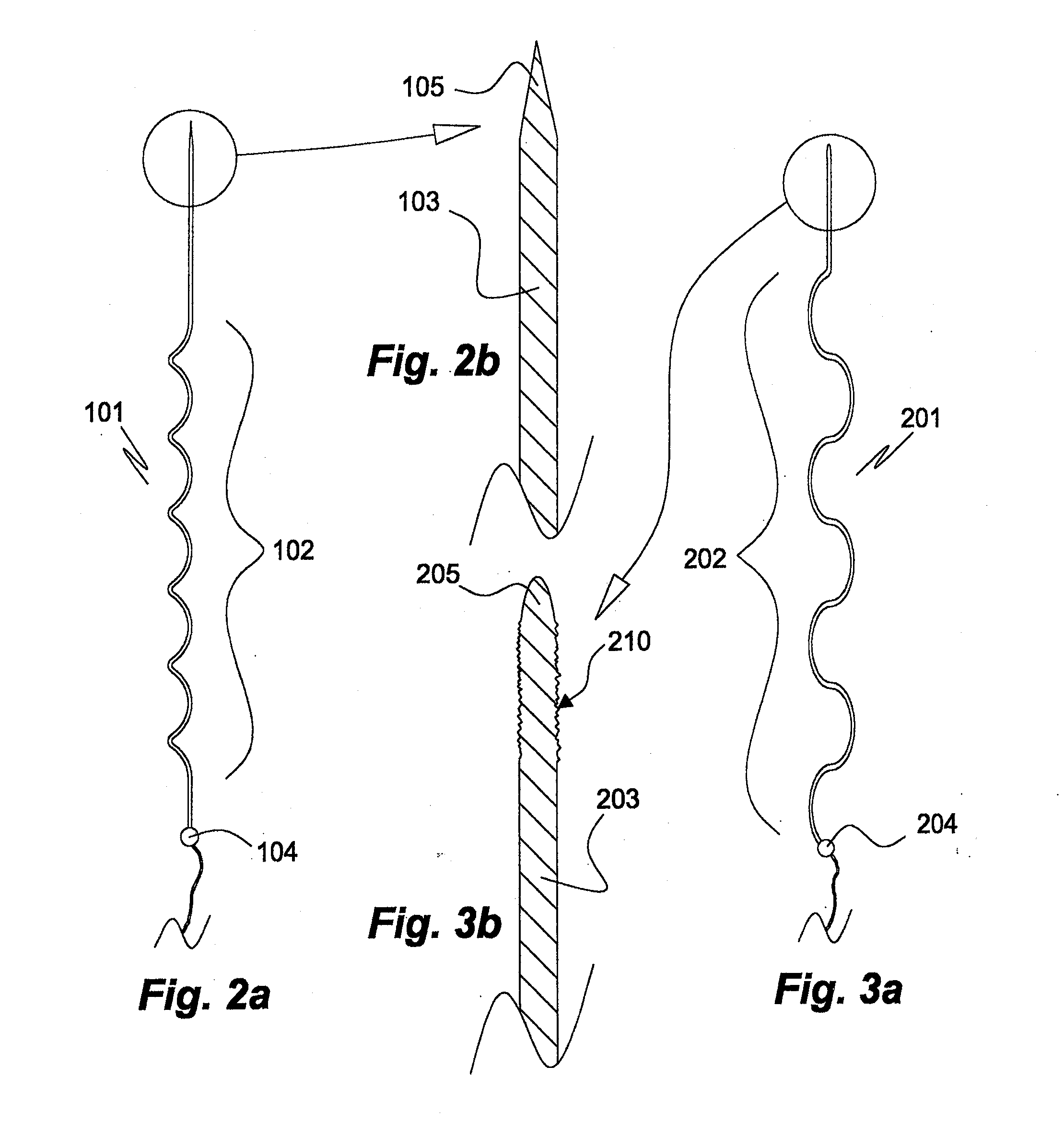
[0151]a matrix-embedded bundle 411 of four electrode bodies of the invention is shown in FIGS. 5a, 5b. The electrode bodies 402a, 403a; 402x, 403c, which are of same kind as that 101 of FIGS. 2a, 2b, are disposed in parallel and equidistantly from the rotational axis S of the bundle 411 in a dissolvable matrix body 412 of sodium hyaluronate comprising a 0.05% (w / w) solid solution of ondansetron, a serotonin (5-HT3) antagonist. In respect of the electrode body 402a of the first electrode, the bodies 402b, 402c, 402d of the other electrodes are disposed in an angle of 90°, 180° and 240°, respectively. In FIG. 5a the tip sections 403a, 403c and the proximal coupling sections 404a, 404c of the first and third electrodes, respectively, are also shown. The generally cylindrically tapering matrix body 412 tapers in a distal direction, only slightly at start but more pronounced towards its distal pointed end 413.

second embodiment

[0152]a matrix-embedded electrode bundle 511 of four electrode bodies of the invention shown in FIG. 6 comprises four electrode bodies 502a, 502b of the kind disclosed in FIGS. 2a, 2b and in the same disposition in respect of a rotational axis S′ as in the matrix-embedded electrode bundle 411 of FIGS. 5a, 5b. In contrast to the embodiment of FIGS. 5a, 5b the matrix body comprises two sections, a proximal section 512′ enclosing the electrode bodies' main sections 502a, 502c, etc., and a distal section 512″ enclosing the tip sections 503a, 503c. The dissolution rate of the proximal matrix body section 512′ is slower than that of the distal matrix body section 512″. This allows, for instance, insertion of the entire matrix-embedded bundle 511 to a desired first depth or level of a soft tissue and, upon dissolution of the distal section 512″ further insertion of the bundle 511 having lost its distal section 512″ to a second depth or level, during which the no longer matrix embedded tip ...

third embodiment

[0155]the electrode bundle of the invention shown in FIG. 13 comprises four longitudinally extendible electrode main body sections 802a, 802c attached to proximal coupling sections 804a, 804c. The bundle is embedded in a dissolvable matrix 812 narrowing towards its distal tip 813. The proximal coupling sections 804a, 804c are moulded in an electrode holder disk 807 from which their rear portions provided with conductors 806a, 806c extend. The electrode holder disk 807 is made of a non-conducting polymer material. This embodiment allows to keep the proximal portions of the electrode main body sections at a desired distance from each other, whereas their distal portions can move more freely in respect of each other. The matrix body 812 of agarose comprises 10% by weight of particulate levodopa 819 dispersed therein.

[0156]A third embodiment of the electrode bundle array of the invention is shown in FIG. 9. The electrode bundle array 920 comprises four matrix-embedded electrode bundles ...


PUM


Abstract

A medical microelectrode includes an elongate electrode body including a tip section, a main body section and, optionally, a coupling section. The tip section, the main body section and, optionally, the coupling section are embedded in a first electrode matrix element, which is substantially rigid, biocompatible and soluble or biodegradable in a body fluid. Additionally the microelectrode includes a dissolution retarding layer on the first electrode matrix element and/or a second electrode matrix element disposed between the first electrode matrix element and the electrode. Upon dissolution or biodegradation of the first electrode matrix element a drug comprised by the first electrode matrix element or the second electrode matrix element is released into the tissue. Also disclosed are bundles and arrays of the electrodes and their use.

Description

FIELD OF THE INVENTION[0001]The invention relates to a medical microelectrode and to multiple medical microelectrodes. In particular, the invention relates to a medical microelectrode, to a bundle of microelectrodes, and to an array of microelectrodes and / or microelectrode bundles. The microelectrode, microelectrode bundle and array of microelectrodes or microelectrode bundles of the invention are intended for insertion into soft tissue such as the brain, the spinal cord, endocrine organs, muscles, and connective tissue.BACKGROUND OF THE INVENTION[0002]Microelectrodes that can be implanted for a long time into the central nervous system (CNS) have a wide field of application. In this invention, the term “electrode” refers to a microelectrode. In principle, all brain nuclei can be recorded from or stimulated by such electrodes and their functions monitored. Of particular importance is the use of a multichannel design in brain nuclei stimulation. In such a design groups of electrodes ...

Claims


Application Information

Patent Timeline
IPC IPC(8): A61M37/00A61B5/24A61B5/291
CPCA61B5/04001A61N1/0412A61N1/0476A61N1/05A61N1/0531A61N1/0536A61L31/16A61N1/306A61N1/325A61N1/327A61N1/37205A61L31/148A61N1/0551A61B5/4094A61B5/24A61K9/50A61B5/291A61L2300/604
Inventor EK, FREDRIKDANIELSEN, NILSERIKSSON LINSMEIER, JENNYPETERSSON, PERSCHOUENBORG, JENS
Owner NEURONANO AB
Why Eureka
Try Eureka