Hybrid frp-concrete-steel double-skin tubular beams and hybrid dstb/slab units using the beams

a technology of concrete-steel and double-skin tubular beams, which is applied in the direction of pillars, structural elements, building components, etc., can solve the problems of high cost, poor corrosion resistance of beam forms, and prone to deterioration and corrosion of both beam forms, so as to achieve excellent corrosion resistance and cost-effective effect, less frp material

Inactive Publication Date: 2012-05-24
THE HONG KONG POLYTECHNIC UNIV
View PDF20 Cites 20 Cited by
  • Summary
  • Abstract
  • Description
  • Claims
  • Application Information

AI Technical Summary

Benefits of technology

[0015]Compared with RC beams and steel beams, the hybrid FRP-concrete steel double-skin tubular beams (DSTBs) according to the invention have a main advantage of excellent corrosion resistance. Compared with types I to IV beams, the advantages of hybrid DSTBs lie in: (1) cost effectiveness because of the use of less FRP material (only a thin outer FRP tube is needed); (2) excellent ductile behavior as the inner steel tube acts as the ductile longitudinal reinforcement. Besides the above two advantages, hybrid DSTBs allow for easier connection to other members than type I beams due to the presence of the inner steel tube and concrete. In addition, the outer FRP tube of the hybrid double-skin tubular beam provides good confinement to the compressive concrete, which is not provided by type II and III beams. Furthermore, the hybrid double-skin tubular beam is lighter than type II and IV beams due to the elimination of redundant tensile concrete.

Problems solved by technology

Undesirably, both beam forms are prone to deteriorating and corrosion in harsh environments, such as in the wild, at the seaside or in a humid environment.
In other words, these beam forms suffer from poor corrosion resistance.
The above-mentioned beam forms suffer from high costs due to the use of a large amount of FRP material as the main longitudinal reinforcement.
In addition, these beam forms suffer from a low stiffness which renders its deformation, instead of its load capacity, the critical concern in design, and poor ductility due to the brittle nature of FRP materials.

Method used


Image

  • Hybrid frp-concrete-steel double-skin tubular beams and hybrid dstb/slab units using the beams
  • Hybrid frp-concrete-steel double-skin tubular beams and hybrid dstb/slab units using the beams
  • Hybrid frp-concrete-steel double-skin tubular beams and hybrid dstb/slab units using the beams

Examples


first embodiment

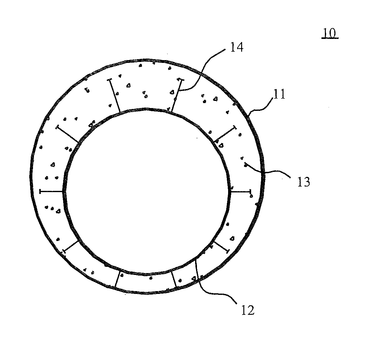
[0023]FIG. 1 depicts the cross sectional structure of the hybrid double-skin tubular beam 10 according to the invention. As shown in FIG. 1, the hybrid double-skin tubular beam 10 is a beam form in the shape of a hollow cylinder, consisting of a circular outer tube 11 made of fiber-reinforced polymer, a circular inner tube 12 made of steel, and concrete 13 filled between the outer tube 11 and the inner tube 12. The outer FRP tube 11 and the inner steel tube 12 are not deployed coaxially in such a way that the inner steel tube 12 shifts a distance towards the side of the hybrid tubular beam 10 that would be tensed. As such, the steel tube can be fully exploited to behave as a material to be longitudinally tensed due to its good ductility. Furthermore, the inner steel tube 12 is provided with a plurality of shear connectors 14 on its side engaged with concrete, which not only ensure the composite action between the inner steel tube 12 and the concrete 13, but also act as positioning s...

second embodiment

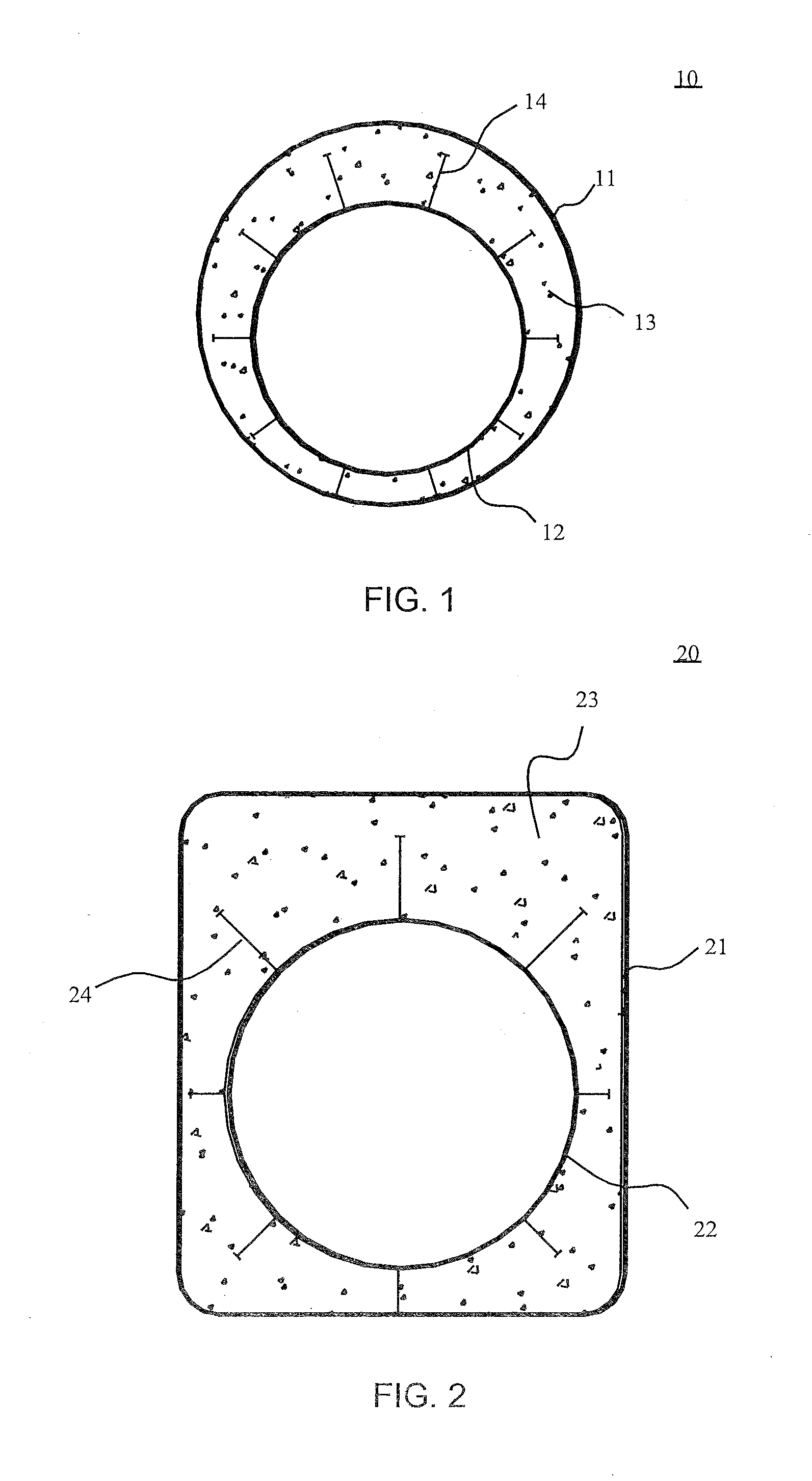
[0024]FIG. 2 depicts the cross sectional structure of the hybrid double-skin tubular beam 20 according to the invention. The hybrid double-skin tubular beam 20 is a beam form in the shape of a hollow rectangular column. Its structure is similar to that of the hybrid double-skin tubular beam 10. As particularly shown in FIG. 2, the hybrid double-skin tubular beam 20 consists of a rectangular outer FRP tube 21, a circular inner steel tube 22, and concrete 23 filled between the outer tube 21 and the inner tube 22. Similarly, the inner steel tube 22 shifts, with respect to the outer FRP tube 21, a distance towards the side of the hybrid tubular beam 20 that would be tensed. As such, the steel tube can be fully exploited to behave as a material to be longitudinally tensed due to its good ductility. Furthermore, the inner steel tube 22 is circumferentially provided with a plurality of shear connectors 24 on its side engaged with concrete, which, on the one hand, ensure the composite actio...

third embodiment

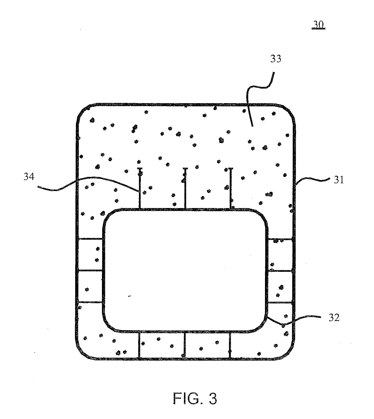
[0025]FIG. 3 depicts the cross sectional structure of the hybrid double-skin tubular beam 30 according to of the invention. The hybrid double-skin tubular beam 30 is a beam form in the shape of a hollow rectangular column. Its structure is similar to those of the hybrid double-skin tubular beam 10 as shown in FIG. 1 and the hybrid double-skin tubular beam 20 as shown in FIG. 2. As particularly shown in FIG. 3, the hybrid double-skin tubular beam 30 consists of a rectangular outer FRP tube 31, a rectangular inner steel tube 32, and concrete 33 filled between the outer tube 31 and the inner tube 32. Similarly, the inner steel tube 32 shifts, with respect to the outer FRP tube 31, a distance towards the side of the hybrid tubular beam 30 that would be tensed. As such, the steel tube can be fully exploited to behave as a material to be longitudinally tensed due to its good ductility. Furthermore, the inner steel tube 32 is circumferentially provided with a plurality of shear connectors ...


PUM


Abstract

This invention relates to a novel hybrid FRP-concrete-steel double-skin tubular beam and a hybrid beam/slab unit which employs the hybrid tubular beam. The hybrid double-skin tubular beam consists of an outer FRP tube, an inner steel tube, and concrete filled between the outer FRP tube and the inner steel tube, and the inner steel tube is provided with a plurality of shear connectors on its side engaged with concrete. The inner steel tube is located eccentrically relative to the outer FRP tube towards the side of the hybrid tubular beam to be tensed. The inventive hybrid beam/slab unit is a slab-on-girder system which is comprised of the hybrid double-skin tubular beam and the lightweight slab of good corrosion resistance (such as a FRP slab or an aluminum slab) that is provided thereon, or a deck or floor system which is comprised of the hybrid double-skin tubular beam and a FRP-rib reinforced concrete slab and in which the upper portion of the hybrid double-skin tubular beam is engaged with the bottom of the FRP-rib reinforced concrete slab thereinside so as to form an integrated body. The inventive hybrid tubular beam features an excellent resistance against corrosion, a good ductility and cost-effectiveness. and is lightweight, while at the same time allows for easy construction and connection with other members.

Description

CROSS-REFERENCE TO RELATED APPLICATIONS[0001]This application claims the benefit of Chinese Patent Application No. 201010180716.6 filed on May 24, 2010, the entire content of which is hereby incorporated by reference.FIELD OF THE INVENTION[0002]The invention relates to loaded members in bridge and construction structures, and particularly, relates to hybrid FRP-concrete-steel double-skin tubular beams (DSTBs) and hybrid DSTB / slab units using the hybrid beams.BACKGROUND OF THE INVENTION[0003]Popular beam forms that are currently widely employed in bridge and construction structures include reinforced concrete (RC) beams and steel beams. Undesirably, both beam forms are prone to deteriorating and corrosion in harsh environments, such as in the wild, at the seaside or in a humid environment. In other words, these beam forms suffer from poor corrosion resistance.[0004]Recently, fibre-reinforced polymer (FRP) composites have been increasingly widely employed for the purpose of solving de...

Claims


Application Information

Patent Timeline
Patent Type & Authority Applications(United States)
IPC IPC(8): E04C3/293
CPCE04B5/046E04C3/34E04B5/43E04B5/026
Inventor TENG, JIN-GUANGYU, TAOWONG, YUK-LUNG
Owner THE HONG KONG POLYTECHNIC UNIV
Why Eureka
Try Eureka