Diffractometer
- Summary
- Abstract
- Description
- Claims
- Application Information
AI Technical Summary
Benefits of technology
Problems solved by technology
Method used
Image

Examples
Embodiment Construction
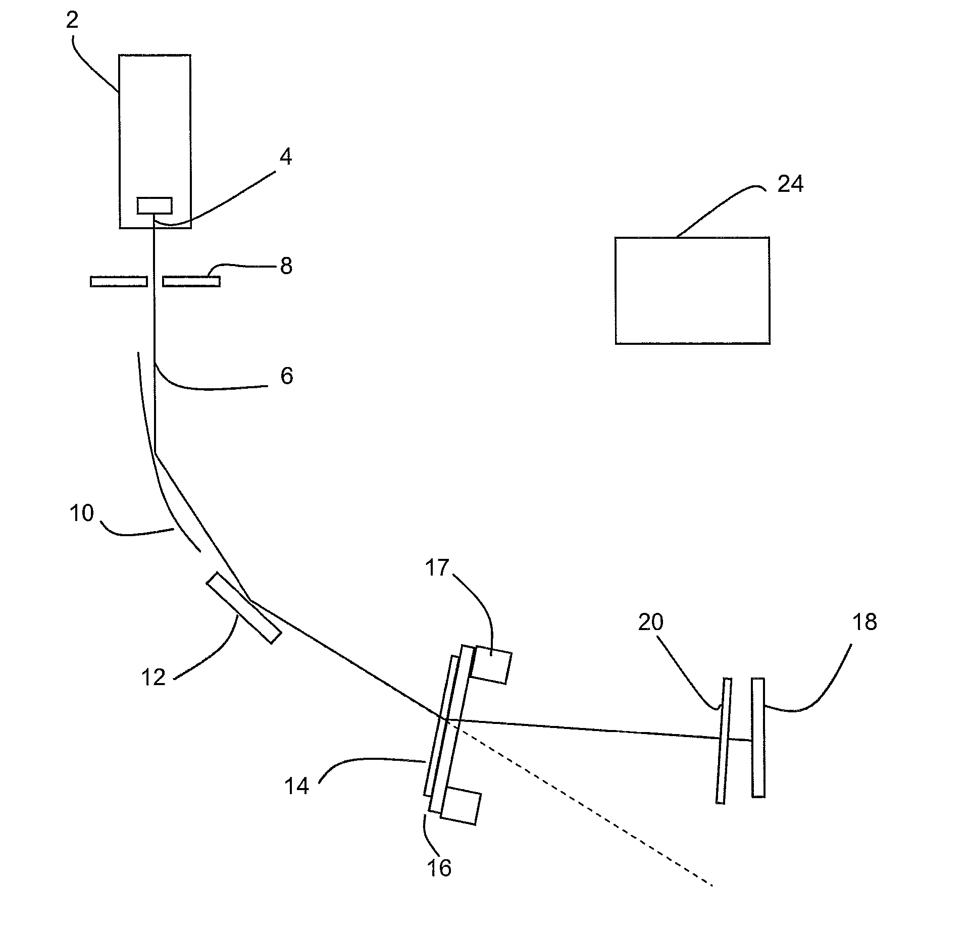
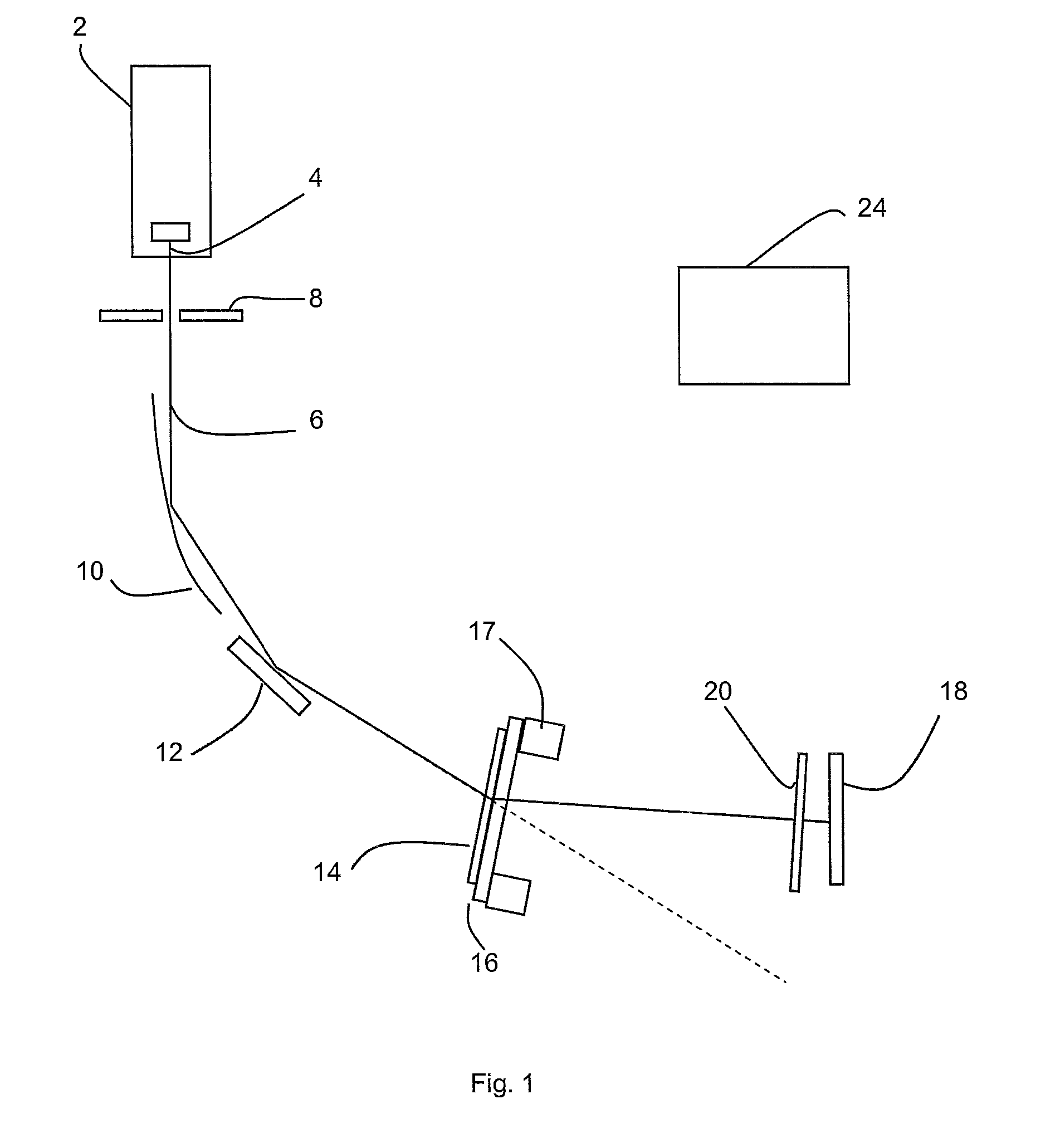
[0037]As shown in FIG. 1, in schematic form, a powder diffractometer according to the invention has an X-ray tube 2 with focus 4 generating a beam 6 of X-rays which is constrained by a divergence slit 8. The beam 6 is directed towards a parabolic mirror 10 which directs x-rays onto a crystal monochromator 12. The parabolic mirror in this case is a periodic multilayer mirror. The X-ray beam is diffracted from the crystal monochromator in a grazing exit condition towards a sample 14 mounted on a piece of adhesive tape 16 as sample holder on sample mount 17.
[0038]A detector chip 18 is arranged to measure the X-rays diffracted from the sample. The detector chip includes a plurality of detector strips arranged as an array.
[0039]The sample mount 17 is capable of rocking.
[0040]The considerations with this geometry will now be discussed in more detail.
[0041]Ideally, as much data as possible will be corrected in parallel. Complications of focusing geometries are to be avoided, as these requi...
PUM
 Abstract
Description
Claims
Application Information
 - R&D
- Intellectual Property
- Life Sciences
- Materials
- Tech Scout
- Unparalleled Data Quality
- Higher Quality Content
- 60% Fewer Hallucinations
Browse by: Latest US Patents, China's latest patents, Technical Efficacy Thesaurus, Application Domain, Technology Topic, Popular Technical Reports.
© 2025 PatSnap. All rights reserved.Legal|Privacy policy|Modern Slavery Act Transparency Statement|Sitemap|About US| Contact US: help@patsnap.com