

Method of making silicon anode material for rechargeable cells
a technology of rechargeable cells and silicon anodes, which is applied in the direction of inorganic chemistry, cable/conductor manufacturing, and manufacturing of electrical components, etc., can solve the problems of difficult handling, time-consuming and expensive silicon etching to form anodes, and difficult to achieve casting and weldability. , the effect of excellent casting ability
- Summary
- Abstract
- Description
- Claims
- Application Information
AI Technical Summary
Benefits of technology
Problems solved by technology
Method used
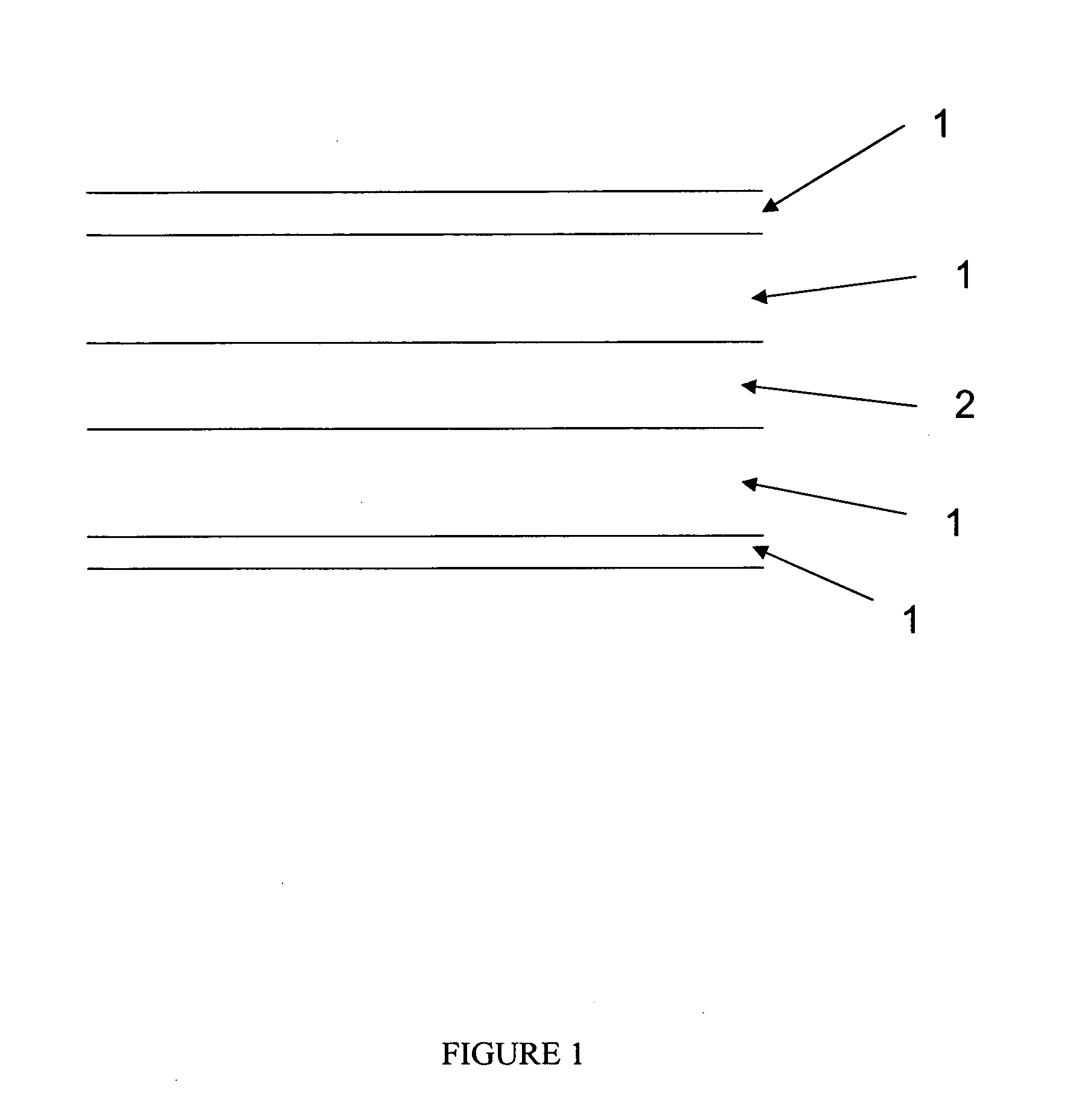
Image

Examples
example 1
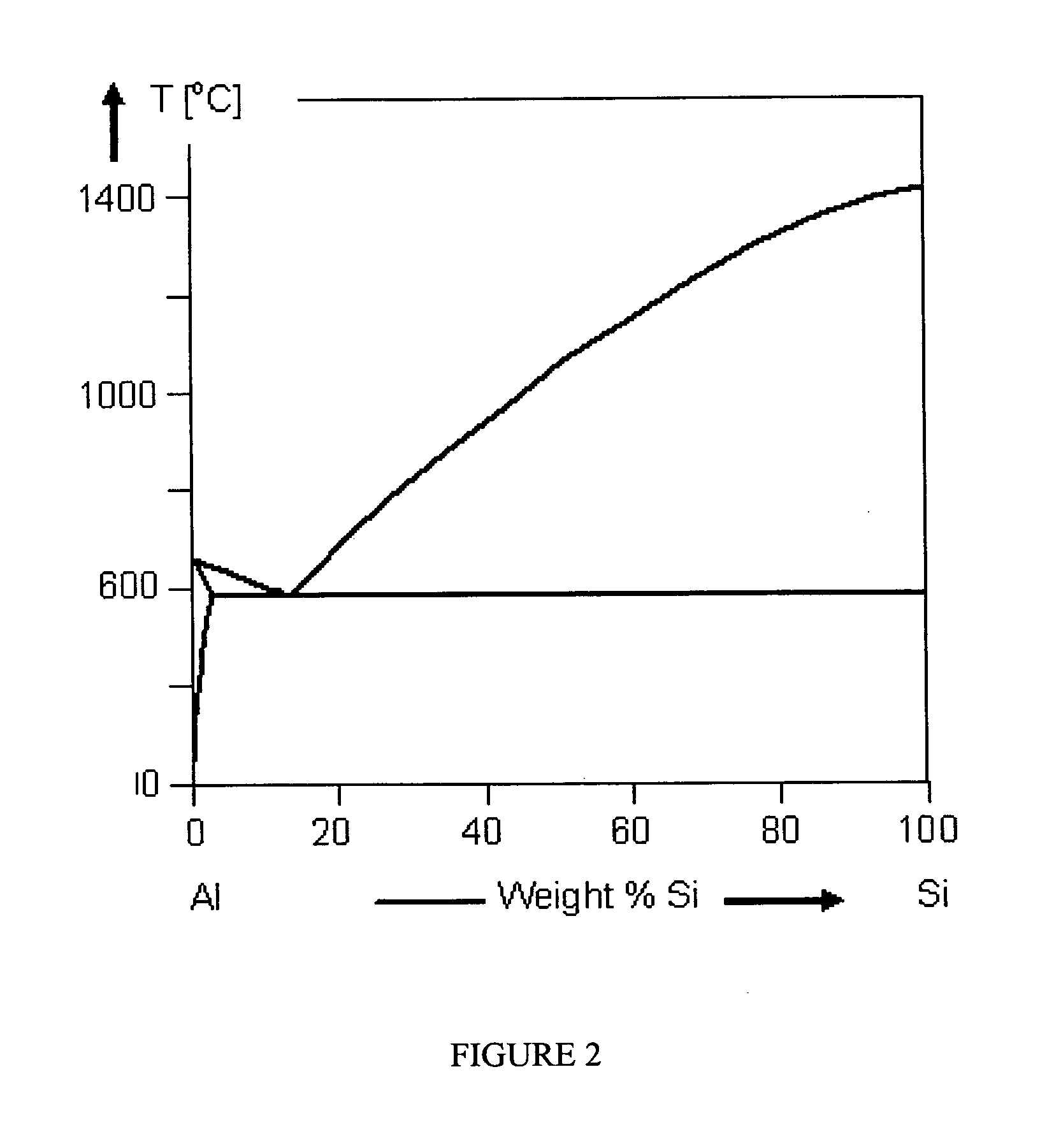
[0045]The steps of etching an aluminium silicon alloy to obtain silicon structures are:[0046]1. Acquire from a foundry or produce an Al—Si alloy with the desired silicon particle structure (rods or plates with smallest dimension 0.1-2 μm, larger dimensions>5 μm). The making of such alloys is commonly applied in industry for making the 4XXX group of aluminium casting alloys (see http: / / www.msm.cam.ac.uk / phase-trans / abstracts / M7-8.html; O. Uzun et al. Production and Structure of Rapidly Solidified Al—Si Alloys, Turk J. Phys 25 (2001), 455-466; S. P. Nakanorov et al. Structural and mechanical properties of Al—Si alloys obtained by fast cooling of a levitated melt. Mat. Sci and Eng A 390 (2005) 63-69). An example would be a commercially available Al—Si 12% alloy as cast that is cooled at a rate of approx 100° Ks−1 and that is subjected to no further post-solidification heat treatment.[0047]2. Etch the aluminium matrix away using a mixed acid reagent or caustic etching, which is a common...
example 2
[0051]1. The starting Al—Si matrix material is particles of Argon or Nitrogen-fired 12 wt % Si—Al alloy with initial particle size ranges 12-63 μm. A typical chemical analysis shows 11.7% Si+3.49% Bi, 0.45% Fe, 0.28% Mn.[0052]2. Use an etch solution having a composition by reactants of: 5 ml concentrated 70% Nitric Acid (15.8M); 3 ml concentrated 36% hydrochloric acid (11.65M); 2 ml 40% hydrofluoric acid; and 100 ml water. The molar composition of the etch solution is therefore: 0.72M nitric acid; 0.32M hydrochloric acid; and 0.41M hydrofluoric acid.[0053]3. Add 1.4 grams of Al—Si alloy per 100 ml etchant to the etchant in an HDPE container with a magnetic follower and stir the alloy / etch mixture at room temperature for 1-2 hours on a slow setting.[0054]4. Turn off stirrer and leave for 16 hours for reaction to go to completion. Silicon structures settle at bottom of reaction vessel.[0055]5. Pour off the spent etch and rinse the silicon structures with deionised water until they are...
example 3
[0057]As Example 2, except using 27.5 wt % silicon and the loading level during etching (step 3) is 1.5 gram per 100 ml etchant.
[0058]FIG. 4 shows a Al—Si structure (27.5 wt % Si) which has been etched in accordance with the above method. As in FIG. 3, the network of fine silicon structures can be observed together with a few larger particulate silicon structures of dimensions 2-5 μm. If the starting amount of silicon in the pre-etched alloy is increased much above 30 wt %, it is expected that the number and size of these larger silicon structures will increase and this is not preferable.
PUM
| Property | Measurement | Unit |
|---|---|---|
| size | aaaaa | aaaaa |
| aspect ratio | aaaaa | aaaaa |
| aspect ratio | aaaaa | aaaaa |
Abstract
Description
Claims
Application Information