SPR optical fiber sensor and SPR sensing device using the same

a technology of surface plasmon and sensing device, which is applied in the direction of optics, optical elements, instruments, etc., can solve the problems of easy restriction of the spr response range, light will not successfully reach the optical detector, and the size of such spr sensing device is huge, so as to promote sensitivity and chemical stability, and widen the spr measurable range.

Inactive Publication Date: 2012-06-07
FORWARD ELECTRONICS CO LTD
View PDF6 Cites 16 Cited by
  • Summary
  • Abstract
  • Description
  • Claims
  • Application Information

AI Technical Summary

Benefits of technology

[0009]The object of the present invention is to provide a surface plasmon resonance (SPR) optical fiber sensor in which two or more layers made of different metals are stacked on the sensing area and thus combination of the SPR responses of the different metals can widen the SPR measurable range to promote sensitivity and chemical stability.
[0010]Another object of the present invention is to provide an SPR sensing device using the SPR optical fiber sensor of the present invention to increase the number of the detectable species of the test samples and the measurable environments.
[0017]The present invention uses two or more metals stacked on the sensing area of the optical fiber substrate and the double- or multi-layered metal structure can be formed by a simple procedure in a chamber of a multi-source evaporation / sputtering apparatus so that the chemical stability and sensitivity of the SPR optical fiber sensor can be promoted. In addition, the SPR sensing device using the abovementioned SPR optical fiber sensor can have expanded detectable species and ranges of the substances.

Problems solved by technology

However, the size of such the SPR sensing devices is huge, and the relative position among the components therein must be accurate.
Otherwise, the metal layer located on the back surface of the prism will not correctly reflect the light emitted from the incidence light processor unit, and the light will not successfully reach the optical detector.
Besides, the metal layer formed by sputtering on the prism is a gold or silver film mostly, and thus it is easy to restrict the range of the SPR response.
Furthermore, when the metal layer is made of other material rather than gold, chemical stability thereof is poor so that the sensitivity of the detection will be easily influenced by the test sample.
Moreover, in order to increase the sensitivity of the abovementioned structure, surface modification is often performed and thus gives complicated procedures of the manufacturing.

Method used


Image

  • SPR optical fiber sensor and SPR sensing device using the same
  • SPR optical fiber sensor and SPR sensing device using the same
  • SPR optical fiber sensor and SPR sensing device using the same

Examples


example 1

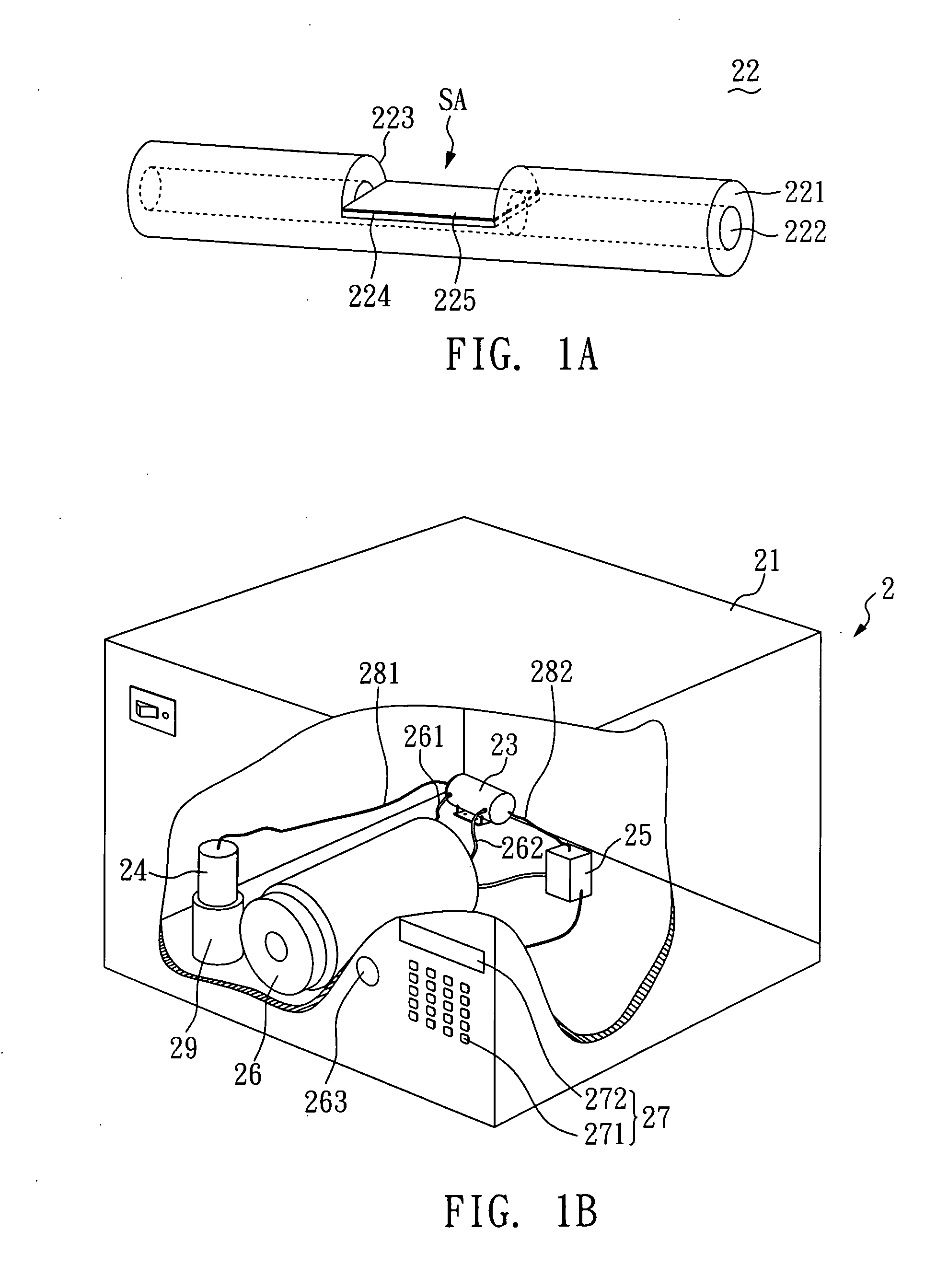
[0026]With reference to FIG. 1A, it is an enlarged view of the SPR optical fiber sensor 22.

[0027]As shown in FIG. 1A, the SPR optical fiber sensor 22 includes a core layer 222, a cladding layer 221 wrapping the core layer 222, a trench 223 exposing the core layer 222, a first metal layer 224 located on the surface of the core layer 222 in the trench 223, and a second metal layer 225 stacked on the first metal layer 224.

[0028]In the abovementioned SPR optical fiber sensor 22, the trench 223 can be formed by side-polishing or etching and can have a length of about 5 mm and a depth of about 62.5 μm. However, the length and depth of the trench 223 is not limited thereto and can be varied according to the species of the test sample and the environmental condition (e.g. refractive index of a solution). Besides, the first metal layer 224 and the second metal layer 225 can be formed on the surface of the trench 223 by DC sputter deposition, RF sputter deposition, evaporation deposition, or ...

example 2

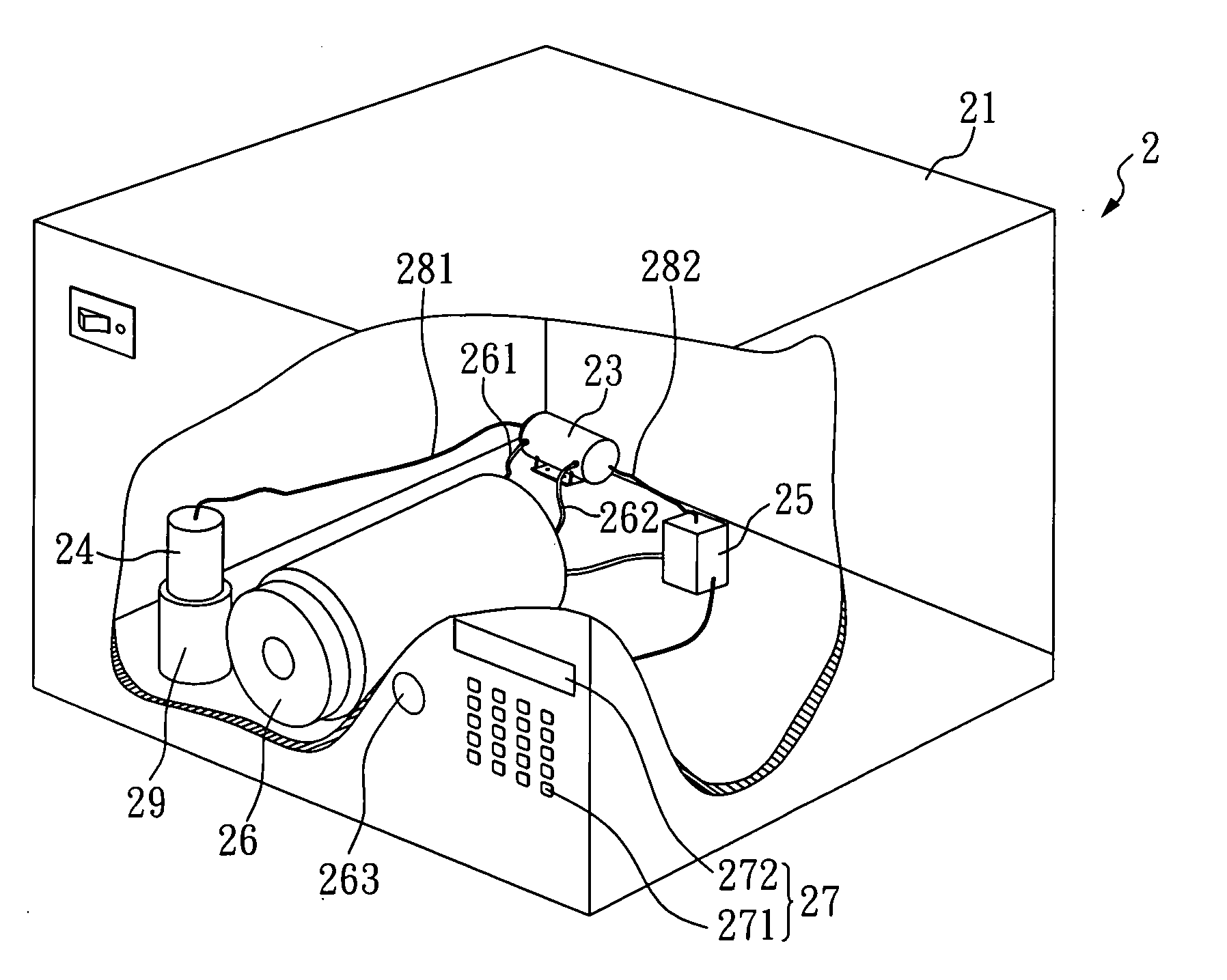
[0030]With reference to FIG. 1B, it is a perspective of the SPR sensing device 2.

[0031]As shown in FIG. 1B, the SPR sensing device 2 of the present invention includes: an outer casing 21, a light source unit 24, a sample tank 23, an SPR optical fiber sensor 22, an optical detector 25, a sample reservoir 26, a calculator-display unit 27, a plurality of optical fibers 281 and 282, and a power unit 29. In the SPR sensing device 2, the SPR optical fiber sensor of Example 1 is employed as the SPR optical fiber sensor and located in the sample tank 23.

[0032]In the present example, the light source unit 24 is a laser diode, and the light source output from the light source unit 24 is transmitted to the light source unit 22 in the sample tank 23 via the multi-mode fiber 281. Subsequently, the photo-signal passing through the SPR optical fiber sensor 22 and carrying the information related to the sample is transmitted to the optical detector 25 by another multi-mode fiber 282. Later, the opt...


PUM

PropertyMeasurementUnit
thicknessaaaaaaaaaa
thicknessaaaaaaaaaa
thicknessaaaaaaaaaa

Abstract

An SPR optical fiber sensor and an SPR sensing device using the same are disclosed. The SPR optical fiber sensor includes: an optical fiber substrate having a sensing area; a first metal layer disposed on the sensing area of the fiber substrate; and a second metal layer which is a gold layer and disposed on the first metal layer. In the present invention, two or more layers of different metals are stacked on the sensing area and thus the SPR measurable range can be promoted to improve the sensitivity and chemical stability of the SPR optical fiber sensor.

Description

BACKGROUND OF THE INVENTION[0001]1. Field of the Invention[0002]The present invention relates to a surface plasmon resonance (SPR) optical fiber sensor and an SPR sensing device using the same and, more particularly, to an SPR optical fiber sensor having multiple stacked metal layers thereon and an SPR sensing device using the same.[0003]2. Description of Related Art[0004]For applications in medical or environmental detection, rapid and accurate identification of the biomolecule species and concentrations is very important. Especially at the hazardous location, the member of the responding staff first has to identify the species and the concentrations of the harmful materials and then decides the subsequent procedures of treatment to minimize the risks based on the detection results. Accordingly, it is dramatically important that the analytical instruments with good accuracy, sensitivity, portability, and simplicity in operation procedures are applied.[0005]Currently, SPR sensing de...

Claims


Application Information

Patent Timeline
Patent Type & Authority Applications(United States)
IPC IPC(8): G01N21/55G02B6/00
CPCG01N21/553B82Y20/00G02B6/1226
Inventor LEE, CHUNG-PEITSAO, YU-CHIACHANG, JUNG-CHIEN
Owner FORWARD ELECTRONICS CO LTD
Why Eureka
Try Eureka