
Image processing method and image processing apparatus for image restoration

Inactive Publication Date: 2012-06-21
CANON KK
View PDF6 Cites 46 Cited by
  • Summary
  • Abstract
  • Description
  • Claims
  • Application Information

AI Technical Summary

Benefits of technology

[0015]The present invention provides an image processing method, an image processing program, an image processing apparatus and an image pickup apparatus that are capable of highly accurately

Problems solved by technology

However, the method disclosed in Japanese Patent Laid-Open No. 06-113309 allows the color shift to remain due to insufficient correction or excessive correction of the color shift when the chromatic aberration of magnification is changed due to manufacturing variation of the optical system or variation of a spectrum characteristic of a light source in image capturing.
However, there is a case where the color shift correction cannot be sufficiently performed even by using the correction method disclosed by Japanese Patent Laid-Open No. 2006-020275.
Thus, the image spread due to influence of the chromatic aberration of magnification of each wavelength that remains in each color component cannot be corrected even if the color shift among the color components can be corrected by the correction method disclosed in Japanese Patent Laid-Open No. 2006-020275.
Thus, the parallel translation of the image of each color component cannot correct the asymmetry.

Method used


Image

  • Image processing method and image processing apparatus for image restoration
  • Image processing method and image processing apparatus for image restoration
  • Image processing method and image processing apparatus for image restoration

Examples


embodiment 1

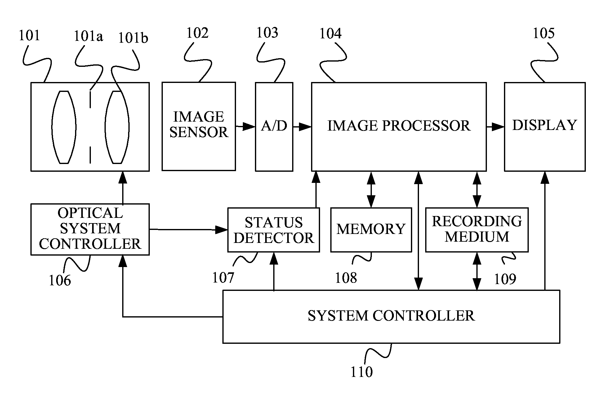
[0092]FIG. 6 shows the configuration of an image pickup apparatus performing image processing according to the image processing method that is a first embodiment (Embodiment 1) of the present invention.

[0093]Light from an object (not shown) passing through an image capturing optical system 101 reaches an image sensor (image pickup element) 102 to form an object image thereon. The object image is converted into an electric signal (analogue signal) by the image sensor 102, and the analogue signal is converted into a digital image pickup signal by an A / D converter 103 and input to an image processor 104 as an image processing apparatus.

[0094]The image processor 104 performs various processes on the digital image pickup signal to produce a captured image as an input image (that is, to acquire the captured image), and performs the above-described image restoration process on the captured image.

[0095]The image processor 104 first acquires, from a status detector 107, information on an ima...

embodiment 2

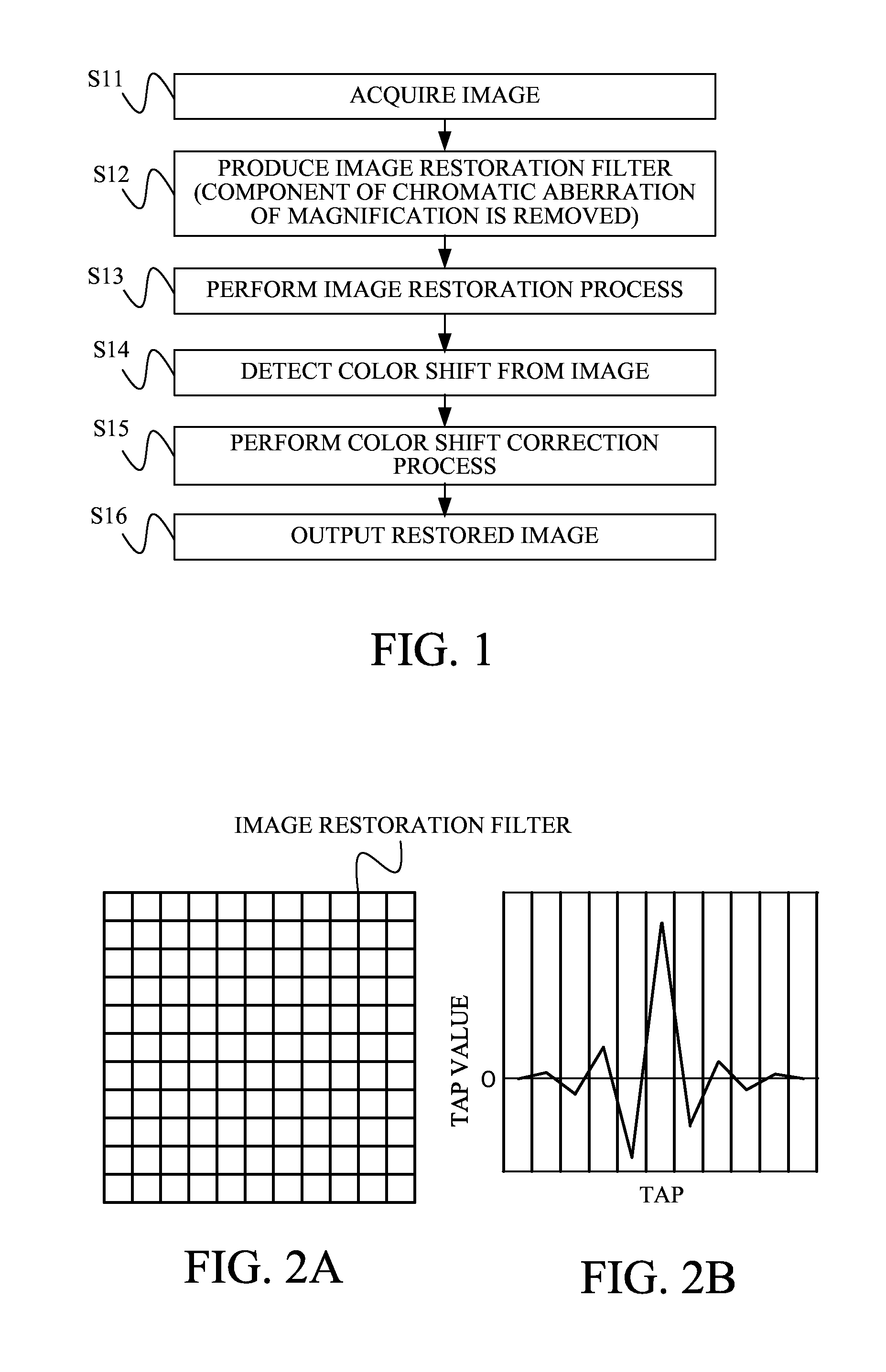
[0134]FIG. 11 shows a flowchart of image processing including an image restoration process performed according to an image processing method that is a second embodiment (Embodiment 2) of the present invention and a color shift correction process. The basic configuration of an image pickup apparatus that performs this image processing is common to that of the image pickup apparatus described in Embodiment 1, so that components of the image pickup apparatus in Embodiment 2 common to those in Embodiment 1 are denoted by same reference numerals as those in Embodiment 1. An image processor 104 as a computer executes the image processing according to an image processing program that is a computer program.

[0135]At step S41, the image processor 104 acquires a captured image that has produced by the image processor 104 itself or that is read from the recording medium 109, as an input image. The image processor 104 also acquires image capturing condition information corresponding to the captu...

embodiment 3

[0169]FIG. 18 shows a system configuration example in a case where the image processing described in each of the above embodiments is performed by an image processing apparatus 201 other than an image pickup apparatus 202.

[0170]The image processing apparatus 201 is a computer in which image processing software 206 including the image processing program described by using the flowchart in each of the above embodiments is installed. The image processing software 206 may include an image data development function and other image processing functions.

[0171]The image pickup apparatus 202 is an apparatus, such as a camera, a microscope, an endoscope and a scanner, which is provided with an image pickup system that photoelectrically converts an object image by an image sensor to produce a captured image.

[0172]A storage medium 203, such as a semiconductor memory, a hard disk or a network server, has a function of storing the captured image.

[0173]The image processing apparatus 201 acquires d...


PUM


Abstract

The image processing method includes a step of acquiring an input image produced by image capturing using an optical system, an image restoration step of performing an image restoration process on the input image to produce a restored image, the image restoration process using an image restoration filter produced based on an optical transfer function of the optical system, and a color shift detection step of detecting color shift included in the restored image, the color shift corresponding to chromatic aberration of magnification of the optical system. The method further includes a restored image color shift reduction step of performing a color shift reduction process on the restored image to reduce the color shift detected in the color shift detection step.

Description

BACKGROUND OF THE INVENTION[0001]1. Field of the Invention[0002]The present invention relates to an image processing technique for reducing an aberration component in an image produced by image capturing.[0003]2. Description of the Related Art[0004]Images produced by image pickup apparatuses such as digital cameras include a blur component (image blur component) that is a component of image degradation caused by various aberrations of an image capturing optical system (hereinafter simply referred to as an “optical system”) such as spherical aberration, comatic aberration, field curvature and astigmatism. Such a blur component is generated because a light flux emitted from one point of an object forms an image with some divergence on an image pickup surface, the light flux being normally converged at one point if there is no aberration or diffraction.[0005]The blur component herein is optically expressed as a point spread function (PSF), and is different from blur caused by defocusin...

Claims


Application Information

Patent Timeline
IPC IPC(8): H04N9/73G06K9/00
CPCH04N9/646H04N9/045H04N25/6153
Inventor HATAKEYAMA, KOSHIKANO, AKIRA
Owner CANON KK
Learn More