
Dynamic bearing device

a bearing device and dynamic technology, applied in the direction of sliding contact bearings, bearing rigid support of bearing units, mechanical apparatus, etc., can solve the problems of increasing the need for a reduction in the cost of a dynamic bearing device, denaturing degeneration in lubricating oil, deterioration of the cleanliness of the bearing device, etc., to achieve sufficient conductivity, improve the effect of reinforcing function and high cleanliness

Inactive Publication Date: 2012-07-12
NTN CORP
View PDF4 Cites 2 Cited by
  • Summary
  • Abstract
  • Description
  • Claims
  • Application Information

AI Technical Summary

Benefits of technology

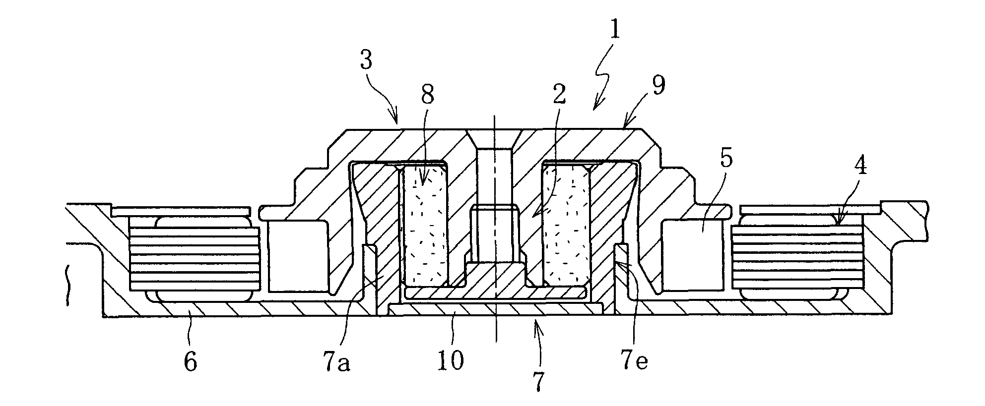
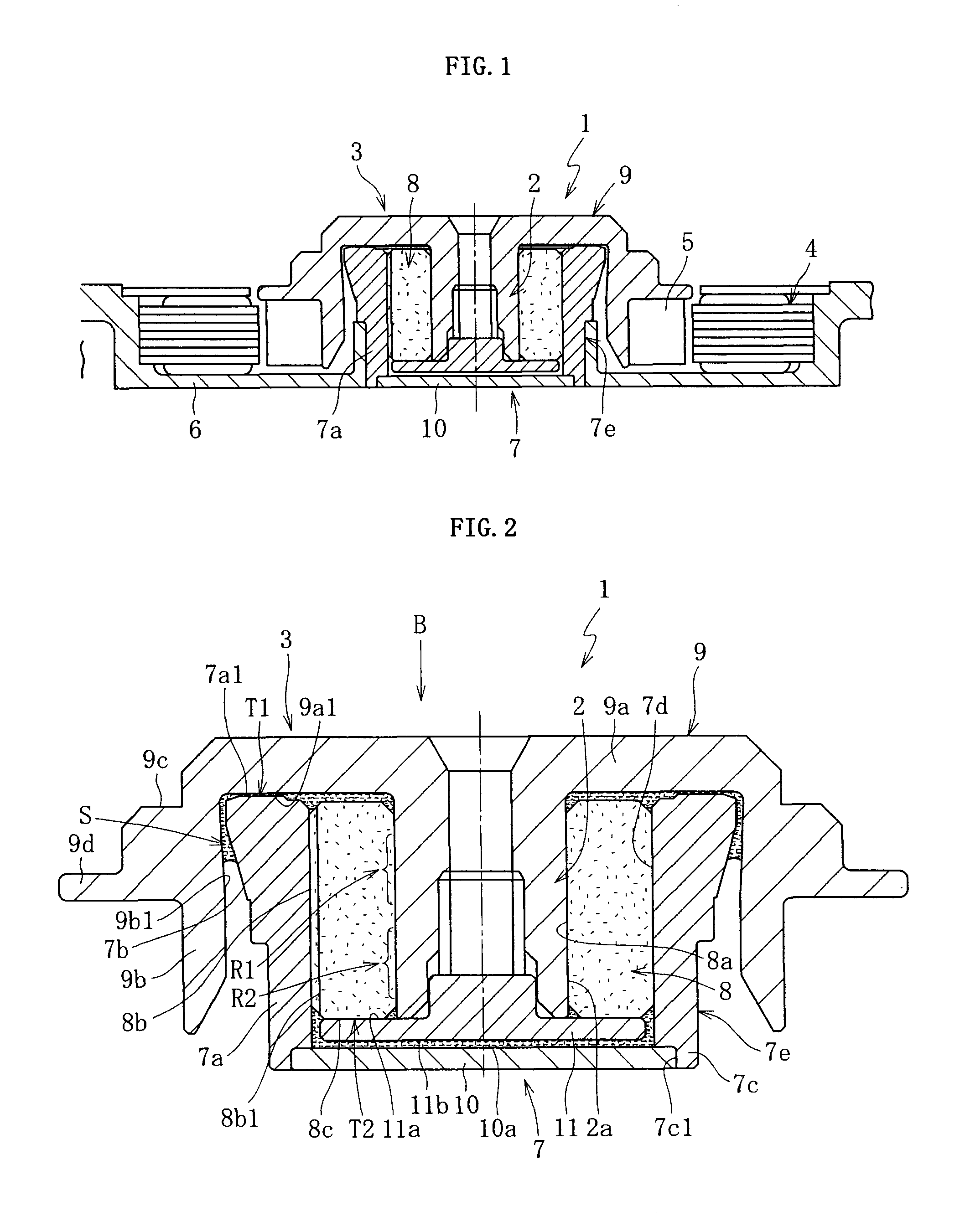
The present invention provides a housing for a dynamic bearing device that is more precise, lighter, and less expensive than previous versions. The housing is made of a resin composition containing polyphenylene sulfide (PPS) as the base resin, which has high oil resistance and low out gas properties. The resin composition also has high strength and impact resistance. Carbon fibers are mixed with the PPS as a filler to enhance the strength of the housing and control the bearing clearance with high accuracy. The carbon fibers have conductivity, which helps dissipate static electricity and maintain the cleanliness of the bearing. The carbon fibers should have a tensile strength of 3000 Mpa or more and an aspect ratio of 6 or more for optimal reinforcing and static electricity removing effects. The filling amount of carbon fibers should be 10 to 35 vol % to ensure sufficient reinforcing and formability of the housing.

Problems solved by technology

At the same time, the requirement for a reduction in the cost of a dynamic bearing device is becoming increasingly severe.
Thus, there is a fear of a product generated through the reaction of the resin material forming the housing with the lubricating oil causing denaturing degeneration in the lubricating oil or a deterioration in the cleanliness of the bearing device.
In particular, in the case of a bearing device to be used in an apparatus for driving a recording disk, such as a hard disk, the out gas generated in the high temperature atmosphere causes a deterioration in the cleanliness of the bearing device or the recording disk driving apparatus, such as contamination of the surface of the hard disk.

Method used


Image

  • Dynamic bearing device
  • Dynamic bearing device
  • Dynamic bearing device

Examples


example 1

[0068]To clarify the usefulness of the present invention, a plurality of resin compositions of different compositions were evaluated in terms of the requisite characteristics of the housing 7. As the base resin, one of different kinds of polyphenylene sulfide (PPS) (one kind of linear type resin and two kinds of cross-linking type resins), polyethersulfone (PES), and polycarbonate (PC) was used. As the filler to be mixed with the base resin, one of three kinds of carbon fibers (two kinds of PAN type fibers and one kind of Pich type fibers) differing in fiber diameter and fiber length (differing in aspect ratios), as shown in FIG. 5A, was used. FIG. 5B shows examples of a combination and mixing ratio of these base resins and fillers (carbon fibers).

[0069]In this example: as the linear type polyphenylene sulfide (PPS), LC-5G manufactured by DAINIPPON INK AND CHEMICALS, INC. was used; as the two kinds of cross-linking polyphenylene sulfide (cross-linking PPSs No. 1 and No. 2), there we...

example 2

[0110]To prove the utility of the present invention, housings 7 were formed using one of polyetheretherketone (PEEK), polyphenylene sulfide (PPS), and polyamide (PA) as the base material, and a material varying in the mixing ratio of carbon fibers, inorganic fibers (aluminum borate whiskers, zinc oxide whiskers), and carbon black as the filler, making comparison in terms of the requisite characteristics of the housings 7.

[0111]In this example, there were used H3110 manufactured by Shinnittetsu Chemical Ind. Co., Ltd. as the ester type lubricating oil, PEEK150P manufactured by Victrex MC Co., Ltd. as the polyetheretherketone (PEEK), Fotron 0220A9 manufactured by Polyplastics Co., Ltd. as the polyphenylene sulfide (PPS), Genesta N1000 manufactured by KURARAY CO., LTD. as the polyamide (PA), Besfite HTA-C6-E manufactured by Toho Tenax Co., Ltd. as the carbon fibers, Alborex Y manufactured by Shikoku Corp. as the aluminum borate whiskers, Panatetra WZ-0501 manufactured by Matsushita Ele...


PUM

PropertyMeasurementUnit
tensile strengthaaaaaaaaaa
aspect ratioaaaaaaaaaa
vol %aaaaaaaaaa

Abstract

Disclosed is a dynamic bearing device which allows production of a smaller housing at low cost and which suppresses ion elution from the resin portion to thereby maintain cleanliness in the dynamic bearing device and exert a desired bearing performance. A dynamic bearing device 1 is equipped with a bearing sleeve 8 fixed to the inner periphery of the housing 7, and a rotary member rotatable relative to the bearing sleeve 8 and the housing 7, in which the rotary member is supported in the radial direction and the thrust direction in a non-contact manner by a dynamic pressure action of a lubricant fluid generated in a bearing clearance. The housing 7 is formed by injection molding of a resin composition containing polyphenylene sulfide (PPS) as the base resin and PAN type carbon fibers as a filler.

Description

CROSS-REFERENCE TO RELATED APPLICATION[0001]This application is a Divisional of application Ser. No. 11 / 659,079, filed Feb. 1, 2007, and wherein application Ser. No. 11 / 659,079 is a national stage application filed under 35 USC §371 of International Application No. PCT / JP2005 / 014034, filed Aug. 3, 2004, which further claims priority of Japanese Application No. 2004-226229, filed Aug. 3, 2004 and Japanese Application No. 2004-227022, filed Aug. 3, 2003, the entire contents of which are incorporated herein by reference.BACKGROUND OF THE INVENTION[0002]1. Field of the Invention[0003]The present invention relates to a dynamic bearing device. This dynamic bearing device are suitable as a bearing device for use in a spindle motor of an information apparatus, for example, a magnetic disc apparatus, such as an HDD, an optical disc apparatus, such as a CD-ROM, a CD-R / RW, or a DVD-ROM / RAM, or a magneto-optical disc apparatus, such as an MD or an MO, a polygon scanner motor for a laser beam pr...

Claims


Application Information

Patent Timeline
Patent Type & Authority Applications(United States)
IPC IPC(8): F16C32/06H02K7/08
CPCB29C45/34B29K2081/04B29K2105/12H02K7/085F16C17/10F16C35/02B29K2707/04F16C17/107F16C2370/12F16C33/10
Inventor MURAKAMI, KAZUTOYOEGAMI, MASAKISHIMAZU, EIICHIROITO, KENJISATOJI, FUMINORI
Owner NTN CORP
Learn More