Switched reluctance motor

a technology of resistor and rotor, which is applied in the direction of dc interrupters, cleaning equipment, cleaning using liquids, etc., can solve the problems of reducing the efficiency of the motor, increasing the cost of the entire system, and increasing the cost of the rotor, so as to reduce the production cost, improve the cleaning performance, and increase the air flow

Inactive Publication Date: 2012-07-12
SAMSUNG ELECTRO MECHANICS CO LTD
View PDF4 Cites 7 Cited by
  • Summary
  • Abstract
  • Description
  • Claims
  • Application Information

AI Technical Summary

Benefits of technology

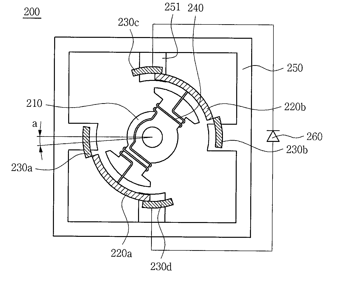
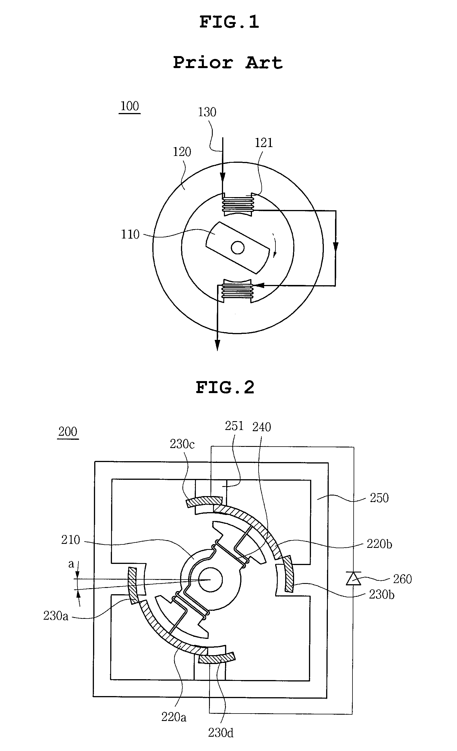
[0010]The present invention has been made in an effort to provide a switched reluctance motor in which a coil is wound around a rotor instead of a stator and only a single phase winding may generate a continuous torque to reduce a production cost due to reduction in a winding, a space part is formed around a stator pole to increase air flow due to increase in a spare area, thereby improving performance of a cleaner, and a torque performing mechanical phase conversion is generated by using a commutator and a brush without using a converter and a position sensor, thereby making it possible to be implemented by a simple mechanical structure at low cost.
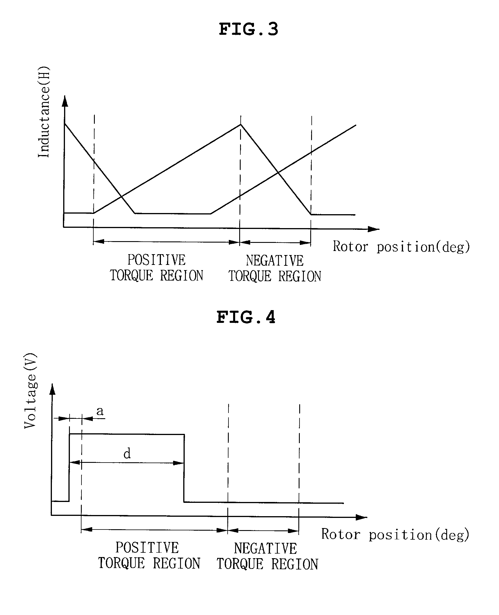
[0011]Further, the present invention has been made in an effort to provide a switched reluctance motor in which an advance angle and a dwell angle having a direct influence on performance of a motor is controlled by changing a position and arc angles of a commutator and a brush, thereby making it possible to perform a design according to an optimal operation point (maximal efficiency, maximal torque, or the like), and respective positive torque regions generated in two pairs of stator poles are controlled using the design method to change an overlapping torque, thereby making it possible to perform a design so as to reduce a torque ripple.

Problems solved by technology

Even though the switched reluctance motor is inexpensive due to a simple rotor structure, it has problems in that it should use a converter formed of a semiconductor switch in order to generate a reluctance torque, has an increased cost of the entire system, and should include an expensive control circuit capable of performing rapid processing in order to appropriately perform a control during rapid driving thereof.
However, in the universal motor, the coil is wound around the rotor as well as the stator, which causes increase in a material cost and copper loss of the rotor, thereby reducing efficiency of the motor.
Therefore, it is difficult to use the universal motor in a high-end type model requiring high efficiency.
In addition, a controller having a digital signal processor (DSP), a microcontroller unit (MCU), or the like, mounted therein is required for complicated and rapid processing.
As described above, since the switched reluctance motor according to the prior art should necessarily include the converter, the controller, and the position sensor for driving thereof, it may not be implemented at a low cost, has a deteriorated degree of freedom in design due to a complicated technical configuration, and has a high possibility for a fault or an error.

Method used


Image

  • Switched reluctance motor
  • Switched reluctance motor
  • Switched reluctance motor

Examples


Embodiment Construction

[0032]Various objects, advantages and features of the invention will become apparent from the following description of embodiments with reference to the accompanying drawings.

[0033]The terms and words used in the present specification and claims should not be interpreted as being limited to typical meanings or dictionary definitions, but should be interpreted as having meanings and concepts relevant to the technical scope of the present invention based on the rule according to which an inventor can appropriately define the concept of the term to describe most appropriately the best method he or she knows for carrying out the invention.

[0034]The above and other objects, features and advantages of the present invention will be more clearly understood from the following detailed description taken in conjunction with the accompanying drawings. In the specification, in adding reference numerals to components throughout the drawings, it is to be noted that like reference numerals designat...


PUM


Abstract

Disclosed herein is a switched reluctance motor including a rotor having a coil wound therearound; commutators connected to both ends of the rotor; brushes mechanically contacting the commutators by rotation of the rotor; and a stator having the brushes fixed thereto and having stator poles, wherein the brushes are moved by an advance angle from a connection axis of stator poles counterclockwise, and a dwell angle, a voltage application period is controlled by arc angles of the commutator and the brush.

Description

CROSS REFERENCE TO RELATED APPLICATION[0001]This application claims the benefit of Korean Patent Application No. 10-2011-0002436, filed on Jan. 10, 2011, entitled “Switched Reluctance Motor”, which is hereby incorporated by reference in its entirety into this application.BACKGROUND OF THE INVENTION[0002]1. Technical Field[0003]The present invention relates to a switched reluctance motor.[0004]2. Description of the Related Art[0005]A general switched reluctance motor has a magnetic structure in which both of a stator and a rotor are a salient pole. In addition, the stator has a concentrated winding coil wound therearound, and the rotor is formed of only an iron core without using any excitation device (e.g., a winding, a permanent magnet, or the like) to have excellent price competitiveness. Further, a speed changeable switched reluctance motor may stably generate a continuous torque with the aid of a converter using a power semiconductor and a position sensor, and may be easily cont...

Claims


Application Information

Patent Timeline
Patent Type & Authority Applications(United States)
IPC IPC(8): H01R39/44
CPCH02K25/00A47L15/0076B08B1/002B08B1/04B08B3/02
Inventor LEE, CHEE WOOBAE, HAN KYUNGLEE, KI YOUNG
Owner SAMSUNG ELECTRO MECHANICS CO LTD
Why Eureka
Try Eureka