
Systems and methods for wavelet and channel-based high definition video encoding

a wavelet and channel-based technology, applied in the field of computer systems, can solve the problems of lossy data compression affecting video quality, severely compromising visual quality, limited trade-space available to meet these requirements, etc., and achieve the effect of high hd quality-preserving compression

Inactive Publication Date: 2012-07-19
EXAIMAGE CORP
View PDF14 Cites 23 Cited by
  • Summary
  • Abstract
  • Description
  • Claims
  • Application Information

AI Technical Summary

Benefits of technology

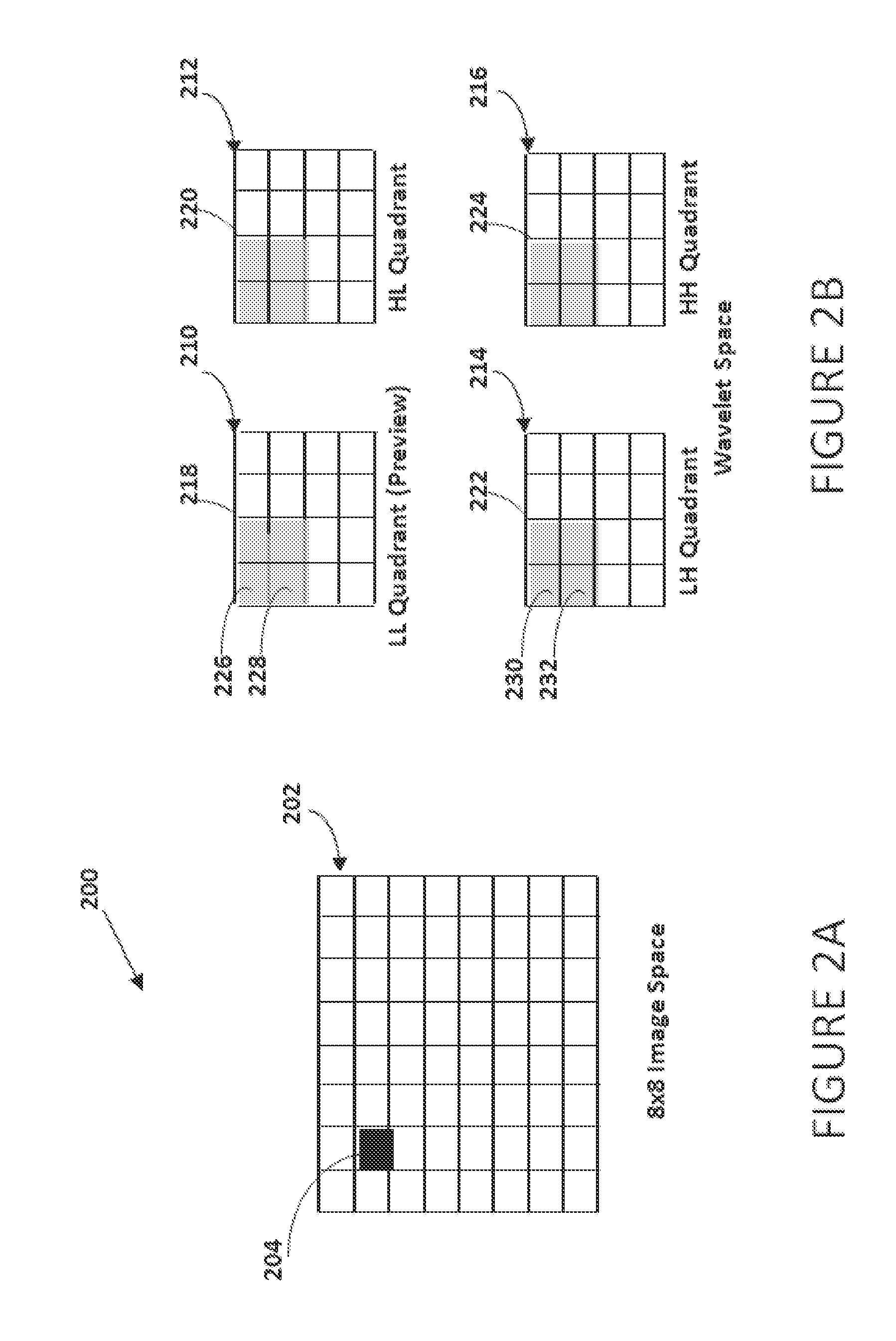
[0011]One or more embodiments of this invention achieve very high HD quality-preserving compression, in part, by extensive use of sophisticated conditional and unconditional replacement of a large proportion of wavelet coefficients generated by the wavelet transform (WT). There are two kinds of wavelet coefficients: ‘preview’ coefficients and ‘support’ coefficients. Most replacement and compression occurs among support coefficients, which may constitute over 95% of the data.
[0013]In the course of compressing video frame data, special filters are applied prior to the WT in order to enhance the effectiveness of these compression techniques. These compression techniques are designed to retain video quality in spite of very high losses of support data during the encoding process. Distinctive wavelet-based techniques and filters are used to capture, retain, and separately encode data most critical to video quality that might otherwise be lost. One or more filters are also applied that eliminate noise that would otherwise interfere with compression of support data. The WT may then be applied to the video frame one or more times. The encoding process allows for the replacement and compression of all support data generated by the first WT application. Each successive application of the WT increases the ratio of support data to preview data by a factor of four, further enhancing opportunities for compression.
[0015]Most encoders are forced to convert red / green / blue (RGB) color video to a particular color space such as YCbCr in order to achieve needed compression. This requires resources of the decoder to convert back to RGB and can reduce the viewing quality of the displayed video. One or more embodiments of this invention require no such conversion and are equally well suited to work with any desired color representation. It may use multiple color spaces, including a new color space, in special ways that further enhance compression of wavelet coefficients. In fact, each data channel, whether or not a color component, is just another data representation of the same image, independent of any other interpretation. This independence simplifies encoding for false color and hyper-dimensional color displays. Other embodiments use certain color spaces for high performance transformation.
[0028]In one or more embodiments, the computer-readable instructions further include the use of a filter for edge restoration. The use of a filter for edge restoration may include iteratively applying the wavelet transform of a video frame n times to obtain preview and support spaces, modifying support space data to maximize compression without regard to loss of edge support data, iteratively applying inverse wavelet transform k times to said preview, 0<k≦n, and said modified support spaces to obtain modified level (n−k) image, generating a pixel-by-pixel difference frame between the original level (n−k) image and the modified level (n−k) image, modifying the difference image by applying at least one edge preserving filter that replaces the values of non-boundary points in said difference frame in order to generate an edge data array, and comprising output data from encoding of said preview, said compressed support spaces, and compressed edge data array, so that the modified level (n−k) image with improved edges is recoverable by decoding the output data and performing pixel-by-pixel summation of the decoded modified level (n−k) image and the decoded edge array.
[0036]In one or more embodiments, the computer readable instructions further include minimizing the number of multiply operations during color space conversion by transforming at least one plurality of video frames to a color space with transformation coefficients comprising sums of dyadic fractions.

Problems solved by technology

The primary issue in video encoding is achieving adequate video compression to satisfy transmission bandwidth and storage media limitations, without too severely compromising visual quality.
Existing video codecs must often trade off viewing quality to satisfy high definition standards, memory limitations and, especially, communication bandwidth limitations.
The trade-space available to satisfy these requirements is limited for codecs based on the discrete cosine transform (DCT).
Because the DCT is suitable only for very small blocks of data, an HD video frame must be partitioned into thousands of distinct DCT blocks, a major processing challenge for the decoder, which must somehow make block boundaries invisible to the viewer.
Such a process makes random access to non-key frames a time-intensive process and makes it difficult to do video editing.
As industry struggles with DCT-based codecs to satisfy even the rudimentary 1280×720p HD standard, with 4320p imminent, there is no clear path to achieving the compression and quality demanded by extra-high definition video.
Wavelet transforms have been applied to compression for still images (e.g., JPEG 2000), but video codecs using wavelets have been found to be too slow and too lacking in viewing quality to be practical even for many non-HD video applications.
Wavelets have been used inefficiently in video codecs (slowing down the decoder) and / or ineffectively (taking only limited advantage of their potential and producing video of inferior quality).
These kinds of implementation problems have discouraged any significant use of wavelets in practical applications and have prevented any use of wavelets in HD or 3-D video applications.
Indeed, existing techniques do not provide compression required for today's standard HD video, nor do they address the loss of video quality typical of wavelet-based codecs.

Method used


Image

  • Systems and methods for wavelet and channel-based high definition video encoding
  • Systems and methods for wavelet and channel-based high definition video encoding
  • Systems and methods for wavelet and channel-based high definition video encoding

Examples


example 1

Landsat Satellite System Hyper-Dimensional Data

[0368]A scientist wishes to examine the effect of seasonal changes in temperature on flora at various altitudes over the course of one or more years. He has a topographic map that provides accurate surface altitudes for the region of interest. Over the period in question, he is able to collect Landsat satellite imagery on a daily basis, from which he is able to extract an infrared image of the region. Finally, he has detailed temperature readings across the region. He collects a year of data into 365 same-time-of-day, properly oriented images. He then encodes and processes them for video display. Either the encoder or the decoder prepares the video for playback on his RGB display. The scientist assigns green to the infrared component, red to the temperature component, and blue to the numerical complement of altitude. He can now watch his video, as it displays the effect of season and temperature on floral life at various altitudes. The ...

example 2

[0372]Description of an implementation of a limited embodiment of systems and methods of wavelet and channel-based high definition video encoding.

[0373]This description mostly follows the sequencing of the FIG. 5 flowchart. In this embodiment, there are three channels (K=3 in step 508), each of them an RGB color channel. A test of the value of the internal parameter representing the PSCR between the current frame and its predecessor reveals that the two 1920×1080 standard high definition video frames are within the same scene shot.

[0374]As in 512 and 516, the next video frame is imported. Channel number k is set to 1 (red), and level number l is set to 0, indicating the video frame is a level 0 image.

[0375]The first operations in step 524 are to isolate and save channel 1 edge data, as described in FIG. 10. In this embodiment, additional edge isolation and compression operations are used that are not described in FIG. 10. Having saved the necessary edge data, there is no further con...

example 3

[0392]Impact of unconditional level 1 zero-substitution, a level 1 noise filter, and conditional level 2 substitution on two-level wavelet encoding compressibility.

[0393]The purpose of this example is to illustrate both the absolute and relative effectiveness of[0394]Process 1: unconditional replacement of all level 1 support data with zeroes,[0395]Process 2: conditional replacement of level 2 support data with zeroes, without the use of Process 3, a level 1 noise filter, and[0396]Process 3: conditional replacement of level 2 support data with zeroes only after Process 3, a noise filter applied to the level 1 image.

[0397]In one or more embodiments of systems and methods of wavelet and channel-based high definition video encoding, the use of a level 1 noise filter is followed by unconditional level 1 zero substitution and conditional level 2 zero substitution. This example describes and illustrates actual results obtained from applying combinations of these methods to the Y color cha...


PUM


Abstract

A wavelet transform (WT) is applied to a data stream of high definition video frames, each comprising one or more data channels digitally representing the same image. A WT is applied to each channel. Visual-quality preserving data filters and data substitution techniques are selectively applied that typically lead to at least 90-to-1 compression of the final encoded video frame. Image edge data is extracted and preserved and image noise is reduced to enhance compressibility. After the first WT, primarily low frequency (LL) image data is retained. With each later WT, more non-LL data is retained. Temporal sequences of LL images that result from the final iteration of the wavelet transform are compressed by means of a chain of invertible differenced images. Any color space can be used. Cross-channel conditional substitution is applicable. Complete multiresolution scalability is incorporated into the encoded product. Extra-high definition video encoding is also achievable.

Description

BACKGROUND OF THE INVENTION[0001]1. Field of the Invention[0002]Embodiments of the invention described herein pertain to the field of computer systems. More particularly, but not by way of limitation, one or more embodiments of the invention enable systems and methods for wavelet-based standard 1080p-high definition and extra-high definition multi-dimensional and channel-based video encoding.[0003]2. Description of Related Art[0004]Video may be stored in digital form. In its uncompressed state, digital video exists as a series of images, or video frames. High definition digital video in its uncompressed state usually involves so much data that it must immediately be either consumed or compressed for transmission or storage, for later decompression and consumption. This problem is resolved with the help of a video encoder that compresses the video to a fraction of its original size. At playback time, with the help of a general or special purpose digital processing device, a correspon...

Claims


Application Information

Patent Timeline
Patent Type & Authority Applications(United States)
IPC IPC(8): H04N7/30
CPCH04N19/00333H04N19/63H04N19/122H04N19/132H04N19/186H04N19/146H04N19/85H04N19/156H04N19/18H04N19/80H04N19/1883H04N19/635H04N19/154H04N19/1887
Inventor MILSTEIN, JAIME
Owner EXAIMAGE CORP
Learn More