Low-profile inducator and its fabrication method

a low-profile, inducator technology, applied in the direction of magnets, inductances, magnetic bodies, etc., can solve the problems of insufficient function design of inductor or choke, low profile characteristics of electronic components, and inability to meet the requirements of low-profile components, so as to save installation space, save labor and time, and low profile characteristics

Inactive Publication Date: 2012-08-02
AJOHO ENTERPRISE
View PDF6 Cites 11 Cited by
  • Summary
  • Abstract
  • Description
  • Claims
  • Application Information

AI Technical Summary

Benefits of technology

[0011]The present invention has been accomplished under the circumstances in view. It is one object of the present invention to provide a low-profile inductor, which has a low profile characteristic, saving much installation space. It is another object of the present invention to provide a low-profile inductor, which is suitable for mass production, saving much fabrication labor and time.

Problems solved by technology

In consequence, electronic component parts must have low profile and small size characteristics, saving circuit board space.
This design of inductor or choke is still not satisfactory in function due to the following drawbacks:1. After winding of the coil B on the core A, the dimension is greatly increased.
When used in a circuit board, the inductor occupies much circuit board space, affecting the circuit arrangement of the circuit board.2. When winding an enameled wire on the core A to form the coil B, it is difficult to control the gap between each two adjacent loops of the coil B. Further, because the coil B is exposed to the outside, it tends to be scratched or damaged by an external object during installation or delivery, affecting the performance.3. Winding an enabled wire on the core A to form the desired coil B must be done manually by labor, complicating the fabrication of the inductor and wasting much labor and time.

Method used


Image

  • Low-profile inducator and its fabrication method
  • Low-profile inducator and its fabrication method
  • Low-profile inducator and its fabrication method

Examples


Embodiment Construction

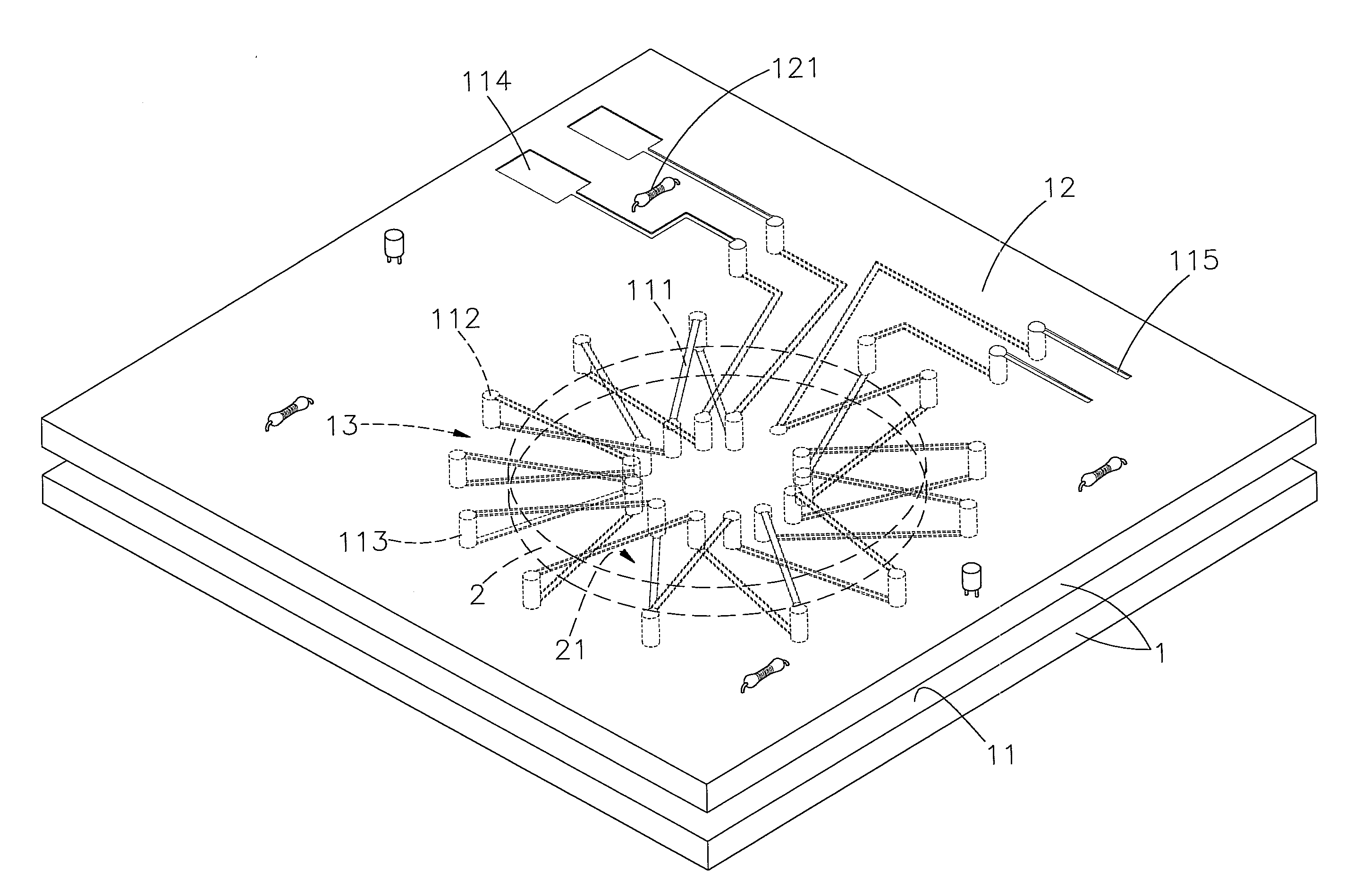
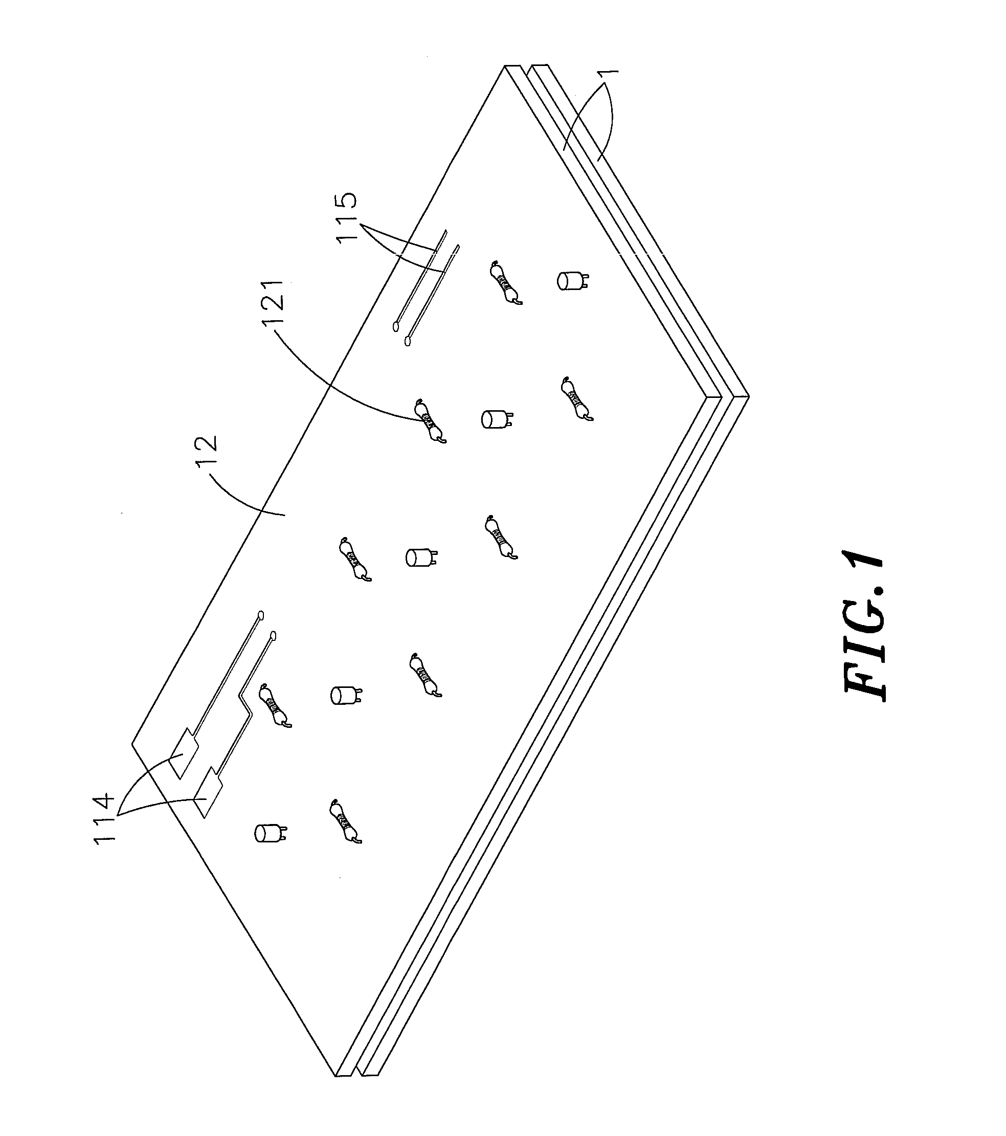
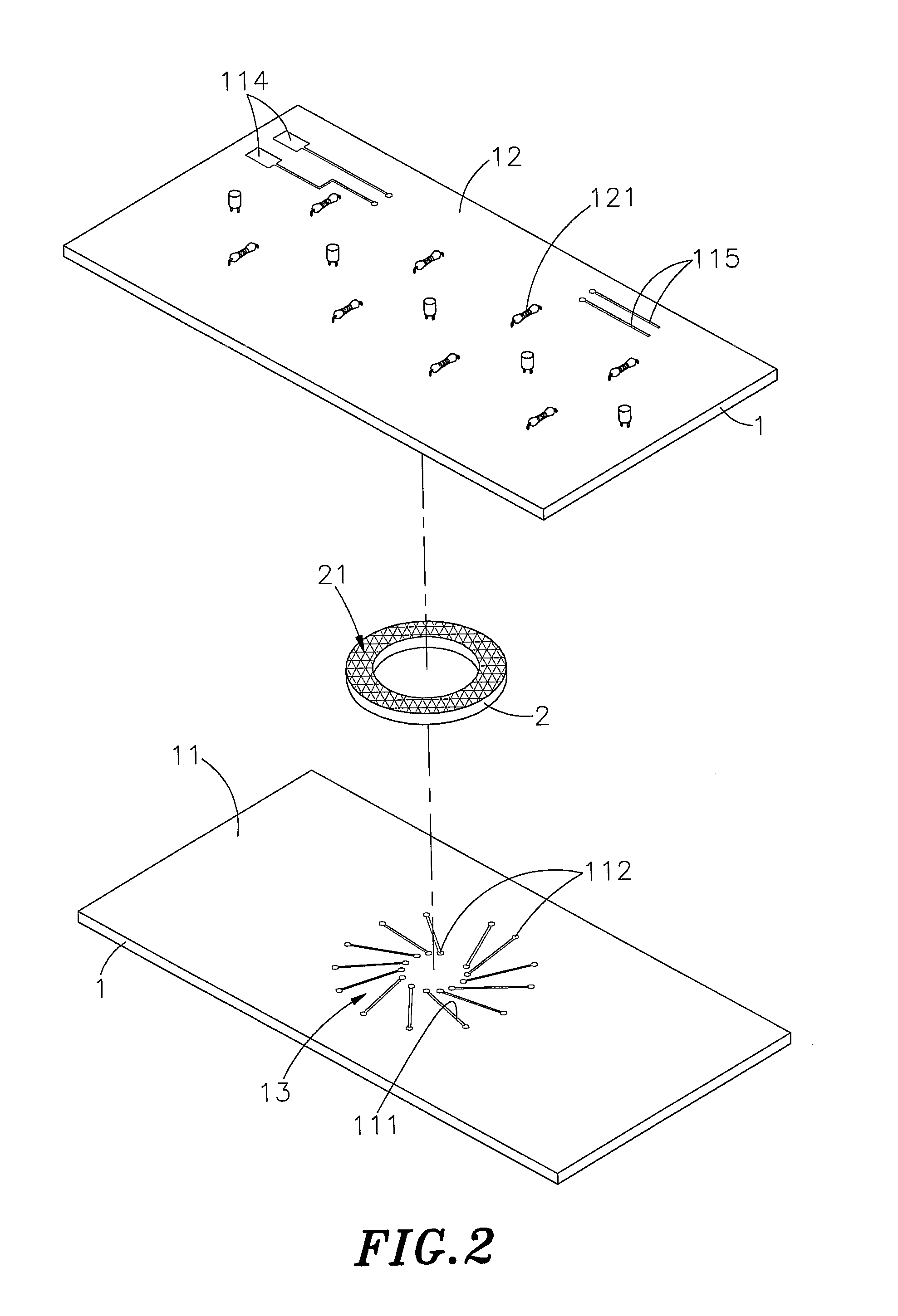
[0024]Referring to FIGS. 1-4, a low-profile inductor in accordance with the present invention is shown comprising two symmetric flat substrates 1 and at least one metal core 2.

[0025]Each flat substrate 1 has opposing inner surface 11 and outer surface 12. Metal wire conductors 111 are radially arranged at the center area of the inner surface 11 of each flat substrate 1, each having a connection contact 112 at each of the opposing ends thereof. The outer surface 12 of each flat substrate 1 provides a circuit layout having a filter function. The circuit layout is an electric loop consisting of different electronic components 121, forming an electrical loop.

[0026]Each metal core 2 is an annular non-crystalline metal core.

[0027]During installation of the inductor, the metal core 2 is set between the metal wire conductors 111 at the inner surfaces 11 of the flat substrates 1 and bonded thereto with an adhesive 21 (the adhesive can be coated on the metal wire conductors 111 at the inner s...


PUM

PropertyMeasurementUnit
electricallyaaaaaaaaaa
sizeaaaaaaaaaa
magnetic fieldaaaaaaaaaa

Abstract

A low-profile inductor includes
    • two flat substrates each flat substrate having opposing inner surface and outer surface, a set of metal wire conductors radially arranged in the inner surface, a connection contact located on each end of each metal wire conductor and a circuit layout arranged in the outer surface, a solder material set in between the flat substrates to electrically connect the connection contacts and the metal wire conductors of the flat substrates into two series, and a metal core bonded to the inner surface of each flat substrate with an adhesive and set between the metal wire conductors of the two flat substrates such that an induction zone is defined between the two flat substrates corresponding to the metal wire conductors to provide a continuous winding type metal magnetic coil inductive effect, enhancing rectifying and filtering performance.

Description

[0001]This application claims the priority benefit of Taiwan patent application number 100103361 file on Jan. 28, 2011.BACKGROUND OF THE INVENTION[0002]1. Field of the Invention[0003]The present invention relates to electrical inductors and more particularly, to a low-profile inductor, which includes two flat substrates electrically arranged in parallel, and a metal core set between a set of radially arranged metal wire conductors at each of the two flat substrates to provide a continuous winding type metal magnetic coil inductive effect, facilitating fabrication and eliminating the drawback of complicated winding procedure of the fabrication of a prior art inductor using an enabled wire winding technique[0004]2. Description of the Related Art[0005]Following fast development of computer technology, many advanced, high-speed. Small-size electronic and electrical products have been created and have appeared on the market. These advanced electronic and electrical products have the comm...

Claims


Application Information

Patent Timeline
Patent Type & Authority Applications(United States)
IPC IPC(8): H01F5/00H01F41/00
CPCH05K1/165H05K2201/086Y10T29/4902H01F17/0033H01F2017/0066H05K2201/09709
Inventor MO, CHIA-PING
Owner AJOHO ENTERPRISE
Why Eureka
Try Eureka