
Method for fabricating semiconductor device

a semiconductor and device technology, applied in the direction of semiconductor devices, basic electric elements, electrical appliances, etc., can solve the problems of difficult control of the threshold voltage of the transistor, defects may be formed inside the silicon substrate, etc., to prevent the transient enhanced diffusion of impurity ions, improve the characteristic of the device, and minimize contact resistance

Inactive Publication Date: 2012-08-16
SK HYNIX INC
View PDF5 Cites 18 Cited by
  • Summary
  • Abstract
  • Description
  • Claims
  • Application Information

AI Technical Summary

Benefits of technology

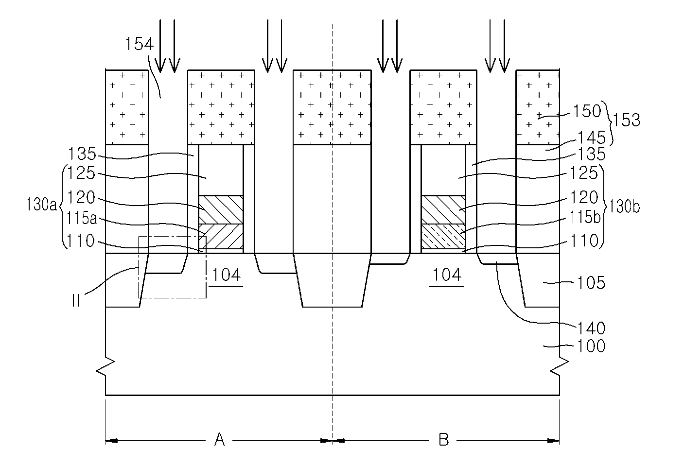
[0007]An embodiment of the present invention relates to a method for fabricating a semiconductor device, which may improve the characteristic of a device by controlling the position of defects formed during an ion implant process, and minimize contact resistance at a contact portion with a contact plug by preventing transient enhanced diffusion (TED) of impurity ions caused by physical damage, thereby implementing a high-speed device.
[0008]In one embodiment, a method for fabricating a semiconductor device includes: forming an impurity junction area within an area of a semiconductor substrate; forming a contact hole which partially exposes a surface of the impurity junction area; and performing an additional ion implant process to implant impurity ions into the impurity junction area exposed through the contact hole, thereby increasing an impurity concentration of a surface portion of the impurity junction area.

Problems solved by technology

However, during the ion implant process to implant a dopant into the silicon substrate, defects may be formed inside the silicon substrate.
Accordingly, it becomes difficult to control the threshold voltage of the transistor.

Method used


Image

  • Method for fabricating semiconductor device
  • Method for fabricating semiconductor device
  • Method for fabricating semiconductor device

Examples


Embodiment Construction

[0023]Hereinafter, embodiments of the present invention will be described with reference to accompanying drawings. However, the embodiments are for illustrative purposes only and are not intended to limit the scope of the invention.

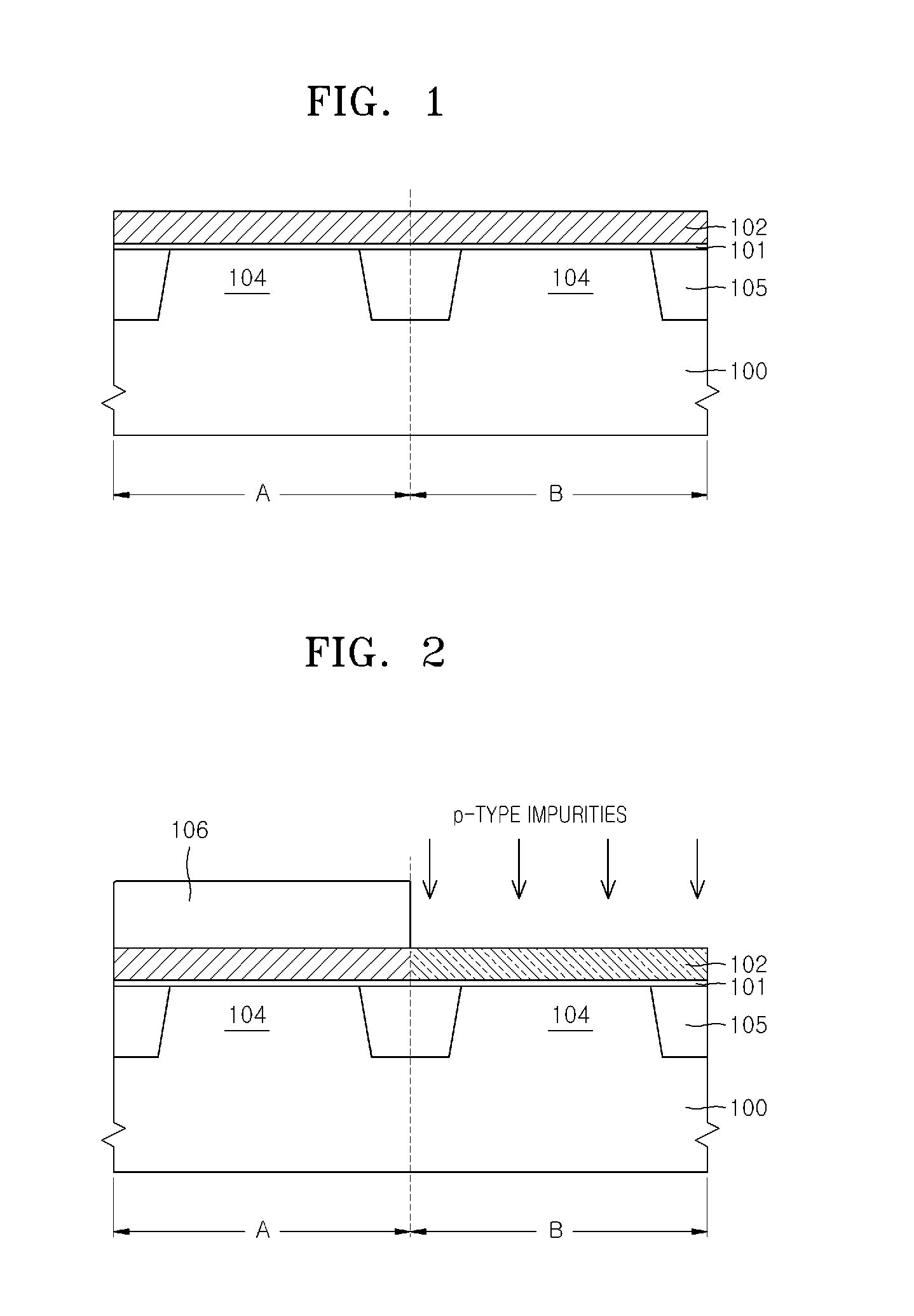
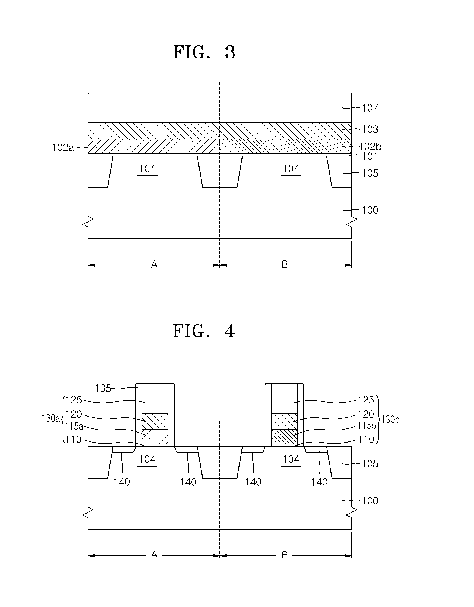
[0024]FIGS. 1 to 13 are diagrams explaining a method for fabricating a semiconductor in accordance with an embodiment of the present invention. In particular, FIG. 9 illustrates defects formed in an active area during a general ion implant process. FIG. 10 illustrates changes in a thickness of an amorphous layer according to a performance temperature of an ion implant process. FIG. 14 is a graph showing concentration distributions of impurity ions according to a temperature during the ion implant process.

[0025]Referring to FIG. 1, a gate dielectric layer 101 is formed over a semiconductor substrate 100 including first and second areas A and B defined therein. Here, the semiconductor substrate 100 is a peripheral circuit area, the first area A is where an ...


PUM


Abstract

A method for fabricating a semiconductor device includes: forming an impurity junction area within an area of the semiconductor substrate; forming a contact hole which partially exposes a surface the impurity junction area; and performing an additional ion implant process to implant impurity ions into the impurity junction area exposed through the contact hole, thereby increasing an impurity concentration of a surface portion of the impurity junction area.

Description

CROSS-REFERENCES TO RELATED APPLICATIONS[0001]The present application claims priority under 35 U.S.C 119(a) to Korean Application No. 10-2011-0012892, filed on Feb. 14, 2011 in the Korean intellectual property Office, which is incorporated herein by reference in its entirety set forth in full.BACKGROUND[0002]1. Field of the Invention[0003]Embodiments of the present invention relate to a method for fabricating a semiconductor device, and more particularly to minimizing defects occurring during the fabrication process.[0004]2. Description of the Related Art[0005]During a semiconductor fabrication process, a channel area is formed inside a silicon substrate, a source area and a drain area of a transistor are defined, and a contact plug is then formed over the silicon substrate. The contact plug may be contacted with the source area and the drain area of the transistor, in order to receive power from outside and supply a current to another device. Typically, the contact plug is formed o...

Claims


Application Information

Patent Timeline
IPC IPC(8): H01L21/8238H01L21/265
CPCH01L21/823814H01L21/823842H01L29/1083H01L21/324H01L29/78H01L21/26506H01L21/26566H01L21/26593H01L21/2658H01L21/265H01L21/26513
Inventor LEE, AN BAEJIN, SEUNG WOOJOO, YUNG HWANJANG, IL SIKCHA, JAE CHUN
Owner SK HYNIX INC
Learn More