Coefficient of thermal expansion filler for vanadium-based frit materials and/or methods of making and/or using the same

a technology of thermal expansion and filler, which is applied in the field of coefficient of thermal expansion filler for glass frit materials, can solve the problems of significant loss, adversely affecting certain low-e coating(s), and long heating time of the entire assembly used in the formulation of edge seals b>4/b>, so as to improve the fit matching to glass expansion, improve the effect of melt flow and improve the effect of sealing

Active Publication Date: 2012-08-23
GUARDIAN GLASS LLC
View PDF3 Cites 59 Cited by
  • Summary
  • Abstract
  • Description
  • Claims
  • Application Information

AI Technical Summary

Benefits of technology

[0020]It also will be appreciated that there exists a need in the art for improved seals and the like that can be integrated with tempered glass units, such as, for example, VIG units. The seals may be designed to allow for reduced temperature sealing such that annealed or tempered glass can be sealed without detrimental impact on the properties of the glass.
[0021]In certain example embodiments, a frit material may provide glass to frit bonding sufficient for VIG purposes (e.g., in terms of structural strength). In certain example embodiments, the provided frit may provide proper glass wetting properties. In certain example embodiments, the frit may seal and have structural strength and a homogenous glassy structure to provide an adequate barrier to prevent vacuum degradation in example VIG units over a period of time.
[0022]In certain instances, improvements in melt flow may enable improved fit matching to glass expansion and / or increase process tolerances to frit bead variations. Improved wetting and bonding properties of a fit material may increase VIG yield by reducing bonding failures of the frit to the glass. A reduction in crystallization may additionally or alternatively facilitate a selected composition to meeting different heating environments (e.g., an internal seal, an external seal, etc).

Problems solved by technology

Unfortunately, the aforesaid high temperatures and long heating times of the entire assembly utilized in the formulation of edge seal 4 are undesirable.
Moreover, such high processing temperatures may adversely affect certain low-E coating(s) that may be applied to one or both of the glass substrates in certain instances.
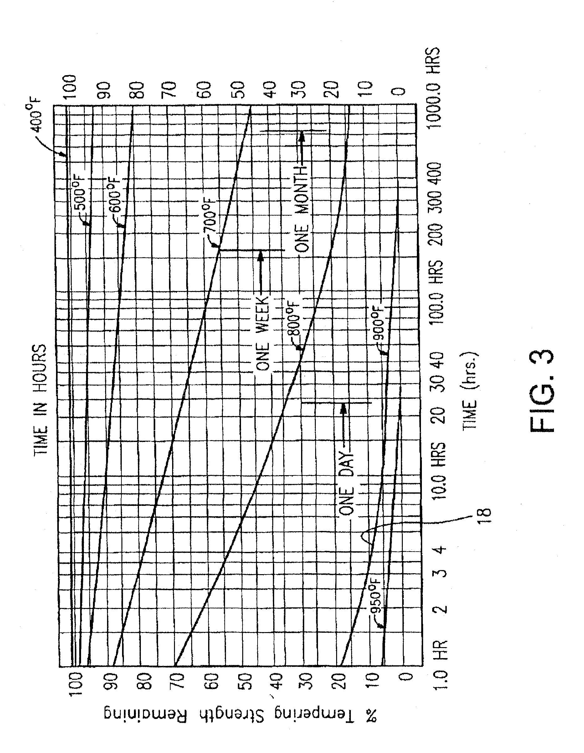
Such a significant loss (i.e., 80% loss) of temper strength may be undesirable.
As shown above, such a temperature can result in a strength reduction for VIG units using tempered glass.
However, in the case of VIG units, epoxy compositions may be insufficient to hold a seal on a vacuum.
Furthermore, epoxies may be susceptible to environmental factors that may further reduce their effectiveness when applied to VIG units.
However, while lead based frits may resolve the above structural issues, the usage of lead in the frit may create new problems.
Specifically, the health consequences to the population for products that contain lead.
This may create a CTE mismatch between the two materials.
This may cause structural problems in a product in which the sealing material is disposed (e.g., bound or adhered) against a substrate.
For example, the sealing material may end up delaminating from the underlying substrate and causing the product to fail (e.g., as the VIG loses vacuum).
As such failure is undesirable, a CTE filler may be added to the sealing material to adjust its expansion rate to bring it closer to (or match) that of the underlying substrate.
However, certain types of frits / glass articles may not have known or acceptable CTE fillers (e.g., a known CTE filler may contain lead above a certain amount), thus making it generally unsuitable for some markets and / or non-compliant with certain standards.
In such situations, the incomplete burn off of a binder may result in a porous frit seal, reduced frit to glass bonding due to, for example, carbon contamination in the frit, or other characteristics that may be undesirable for frit based seals.

Method used


Image

  • Coefficient of thermal expansion filler for vanadium-based frit materials and/or methods of making and/or using the same
  • Coefficient of thermal expansion filler for vanadium-based frit materials and/or methods of making and/or using the same
  • Coefficient of thermal expansion filler for vanadium-based frit materials and/or methods of making and/or using the same

Examples


example 1

[0099]A methyl cellulose polymer binder. Example 1 included 0.75 wt % methyl cellulose (400 cps molecular weight polymer) in DI water. TGA analysis of this material indicated a burn out of the binder at around 320-380° C.

example 2

[0100]A polyethylene carbonate binder, for example, [CH2CH2OCO2]n or C3H4O3. One example of such a binder is available under the material trade name QPAC® 25 from Empower Materials Inc. It will be appreciated that other carbonate inclusive binder materials may be used in certain example embodiments.

example 3

[0101]A polypropylene carbonate binder, for example, [CH3CHCH2OCO2]n or C4H6O3. One example of such a binder is available under the material trade name QPAC® 40 from Empower Materials Inc. As noted above, in FIG. 13, TGA analysis of these examples 2 and 3 indicated that the burnout of the binder material may be around 250-275° C.

[0102]The examples shown in FIGS. 14B, 15B, 16B, and 17-19 included a 5:1 (gram) ratio frit-to-binder solution. These were dried into layers on microscope slides, and the slides were placed on a 71 / 38 coated glass. It will be appreciated that this ratio of fit to binder solution is given by way of example and that other ratios may be used. For example, the ratio may be between ratios of 4:1 and 6:1.

[0103]FIGS. 14A, 15A, and 16 are temperature vs. time graphs that each show various temperatures at varying times of an example fit material, a duct temperature (e.g., where the IR energy is applied), and two glass substrates that are respectively coated (e.g., wi...


PUM

PropertyMeasurementUnit
sizeaaaaaaaaaa
sizeaaaaaaaaaa
average diameteraaaaaaaaaa

Abstract

Certain example embodiments relate to seals for glass articles. Certain example embodiments relate to a composition used for sealing an insulted glass unit. In certain example embodiments the composition includes vanadium oxide, barium oxide, zinc oxide, and at least one additional additive. For instance, another additive that is a different metal oxide or different metal chloride may be provided. In certain example embodiments, a composition may be combined with a binder solution that substantially or completely burns out by the time the composition is melted. In certain example embodiments, a CTE filler is included with a frit material. In certain example embodiments, a vacuum insulated glass unit includes first and second glass substrates that are sealed together with a seal that includes the above-described composition.

Description

CROSS REFERENCE TO RELATED APPLICATION[0001]This application is a continuation-in-part of U.S. Application No. 13 / 339,463, filed Dec. 29, 2011, which is a continuation-in-part of U.S. Application No. 13 / 238,358, filed Sep. 21, 2011, which is a continuation-in-part of U.S. application Ser. No. 12 / 929,875, filed Feb. 22, 2011, the entire contents of which are each hereby incorporated by reference.FIELD OF THE INVENTION[0002]Certain example embodiments of this invention relate to coefficient of thermal expansion (CTE) fillers for glass frit materials. More particularly, certain example embodiments relate to fillers that are usable with vanadium-based frit materials. In certain example embodiments the fillers and frit materials may be used for glass articles (e.g., for use in vacuum insulated glass or VIG units), and / or methods of making the same, as well as articles including such frit materials and fillers and / or methods of making the same. In certain example embodiments, frits with C...

Claims


Application Information

Patent Timeline
Patent Type & Authority Applications(United States)
IPC IPC(8): E06B3/66C03C17/04C03B23/203C03C8/24C03B19/10
CPCC03C8/24C03C8/04C03C2207/00E06B3/6612E06B3/663E06B3/66342E06B3/67391Y02A30/249Y02B80/22
Inventor DENNIS, TIMOTHY A.
Owner GUARDIAN GLASS LLC
Why Eureka
Try Eureka