Antenna sharing device
a technology of sharing device and duplexer, which is applied in the direction of impedence network, electrical apparatus, piezoelectric/electrostrictive/magnetostrictive devices, etc., can solve the problems of narrow transmission bandwidth, increased loss in a wide transmission passband, and difficulty in maintaining a small loss in the wide transmission passband. achieve the effect of smooth crossband and low loss characteristi
- Summary
- Abstract
- Description
- Claims
- Application Information
AI Technical Summary
Benefits of technology
Problems solved by technology
Method used
Image
Examples
first exemplary embodiment
[0066]A first exemplary embodiment of the present invention will now be described with reference to the drawings.
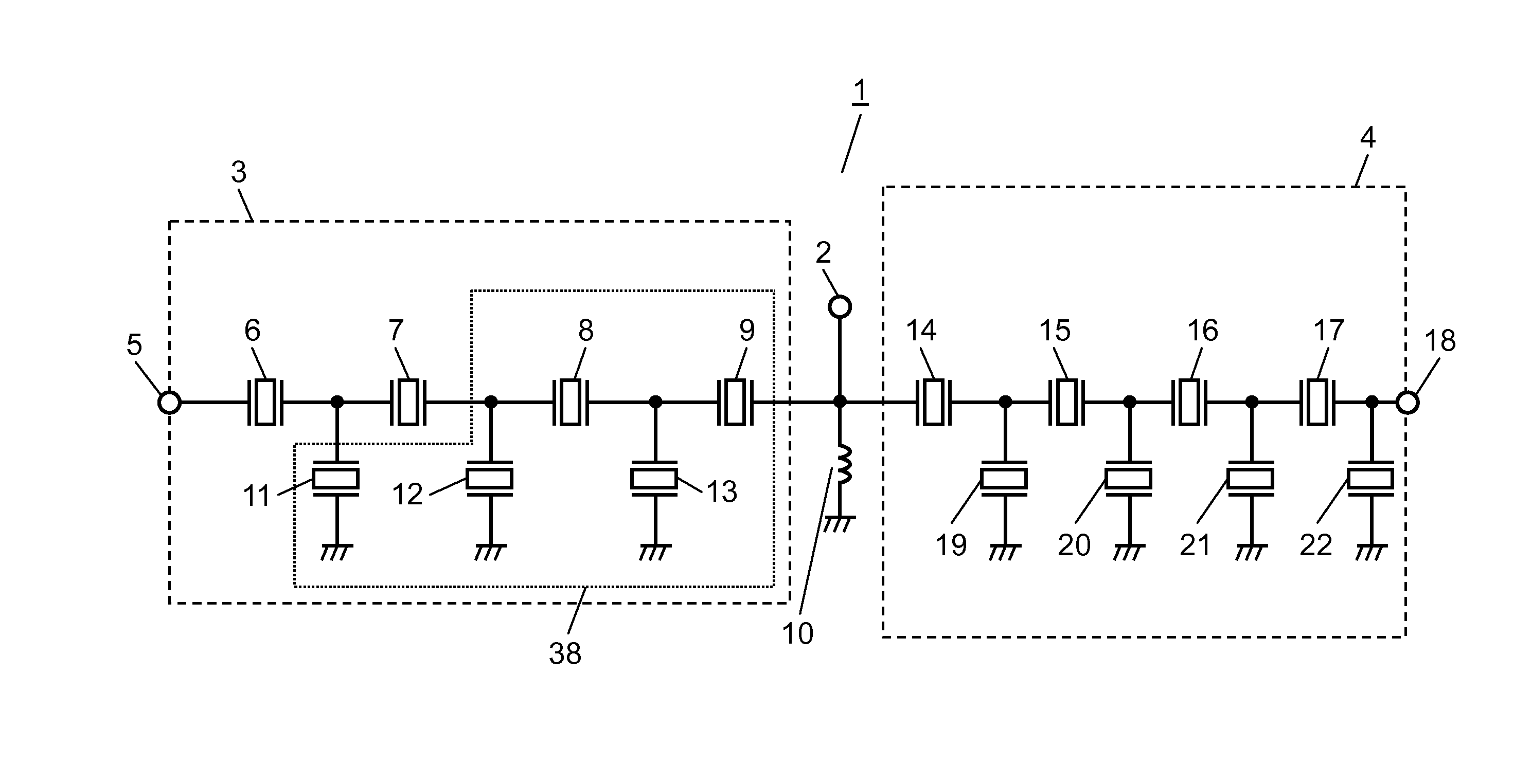
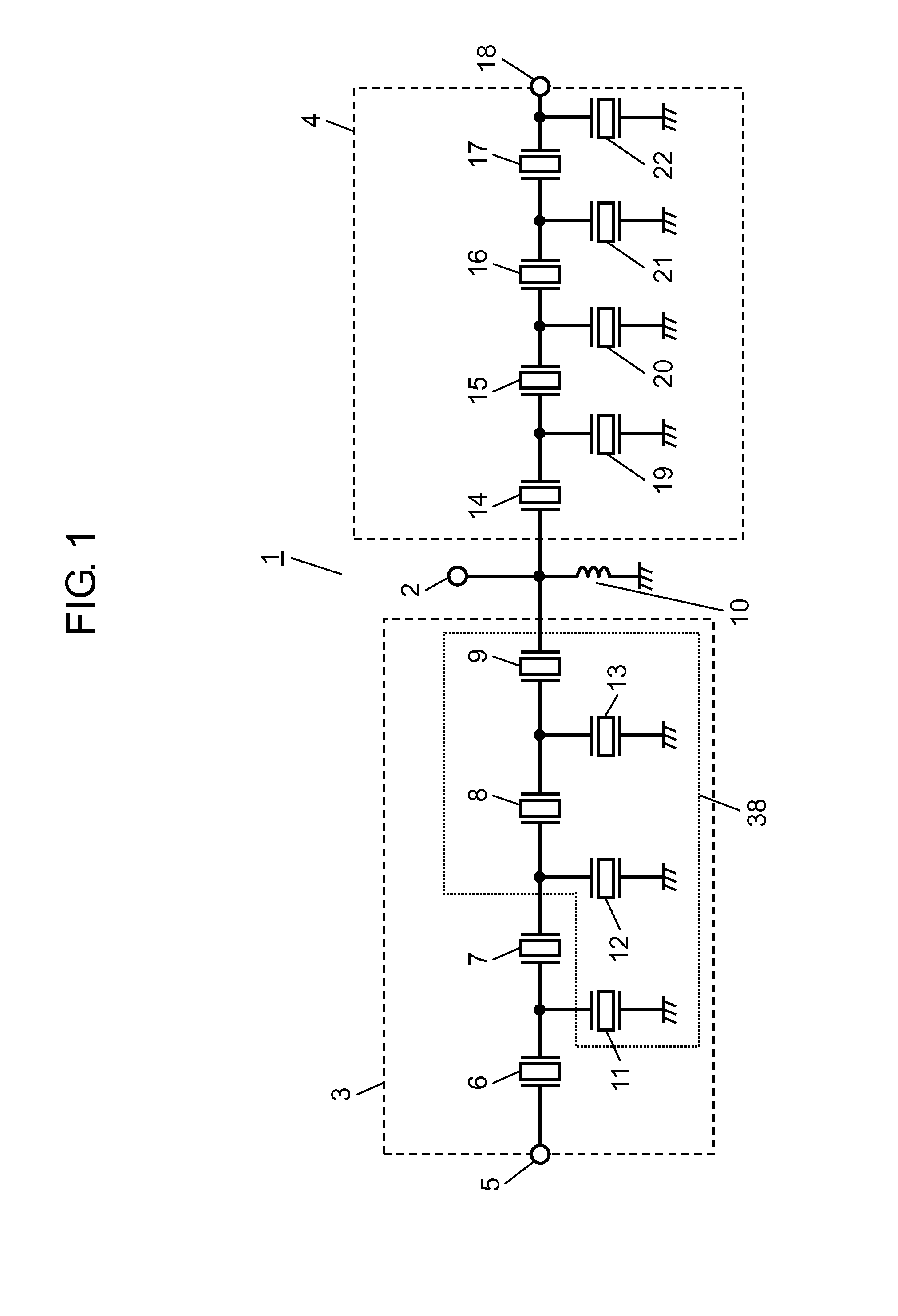
[0067]FIG. 1 is a schematic circuit diagram of antenna duplexer 1 in the first exemplary embodiment of the present invention.
[0068]Antenna duplexer 1 in the embodiment has first filter 3 as a transmission filter and second filter 4 as a reception filter each connected to antenna terminal 2. Antenna duplexer 1 has phase shifter 10 connected between first and second filters 3 and 4 to assure isolation between first and second filters 3 and 4.
[0069]Antenna duplexer 1 is, for example, for band 2. First filter 3 passes a signal in a first frequency band (transmission band) of 1850 MHz to 1910 MHz, and second filter 4 passes a signal in a second frequency band (reception band) of 1930 MHz to 1990 MHz higher than the first frequency band.
[0070]The circuit configuration of each of first and second filters 3 and 4 will now be described specifically.
[0071]First filter 3 has input t...
second exemplary embodiment
[0129]A second exemplary embodiment of the present invention will now be described.
[0130]FIG. 20 is a schematic circuit diagram of antenna duplexer 51 in the second exemplary embodiment of the invention.
[0131]FIG. 21 is a schematic cross section of first filter 53 in antenna duplexer 51 in the second exemplary embodiment of the invention. Antenna duplexer 51 in the embodiment has, like antenna duplexer 1 shown in FIG. 1, first filter 53 and second filter 4. Unless otherwise specially described, the configuration of first filter 53 is similar to that of first filter 3 of the first embodiment.
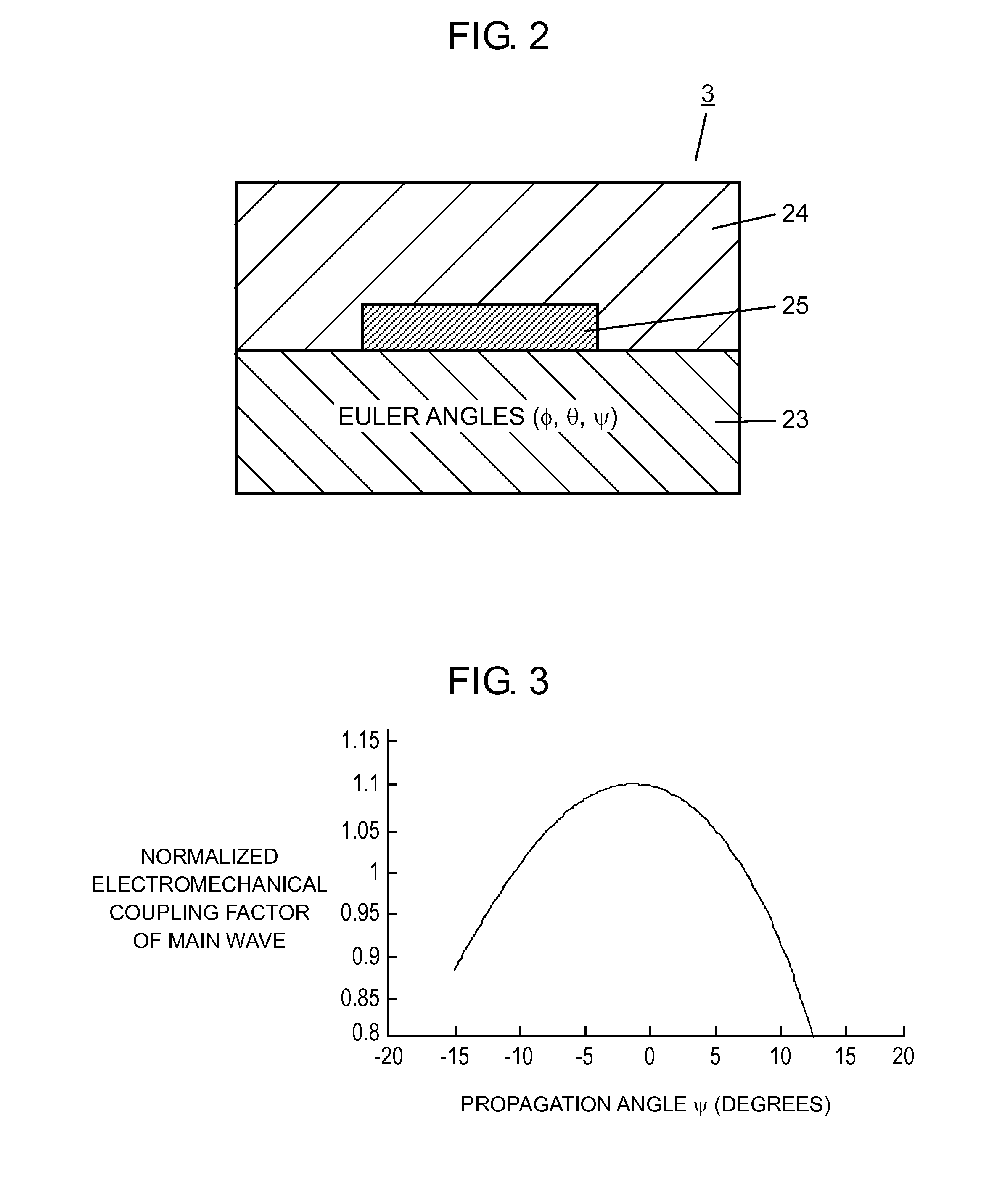
[0132]First filter 53 in the embodiment has piezoelectric body 23 made of a lithium niobate based body having the Euler angles (φ, θ, ψ), electrode 25 provided on piezoelectric body 23 and exciting the main elastic wave having wavelength X, and protective film 24 formed on piezoelectric body 23 so as to cover electrode 25 and having thickness larger than 0.2 λ.
[0133]Protective film 24 has project...
third exemplary embodiment
[0155]Next, a third exemplary embodiment of the present invention will be described.
[0156]FIG. 24 is a schematic circuit diagram of antenna duplexer 61 in the third embodiment of the present invention.
[0157]In the embodiment, the configuration of first filters 3 and 53 described in the first and second exemplary embodiments is applied to second filter 54 of antenna duplexer 61.
[0158]Concretely, the resonance frequency of fourth parallel resonator 19 in second filter 54 is set to be higher than that of the other parallel resonators, concretely, fifth, sixth, and seventh parallel resonators 20, 21, and 22. The electromechanical coupling coefficient of fourth parallel resonator 19 is set to be smaller than that of fifth, sixth, and seventh parallel resonators 20, 21, and 22. Consequently, the propagation angle ψ of the main elastic wave of fourth parallel resonator 19 is made different from that of the main elastic wave of fifth, sixth, and seventh parallel resonators 20, 21, and 22.
[0...
PUM
 Abstract
Description
Claims
Application Information
 - R&D
- Intellectual Property
- Life Sciences
- Materials
- Tech Scout
- Unparalleled Data Quality
- Higher Quality Content
- 60% Fewer Hallucinations
Browse by: Latest US Patents, China's latest patents, Technical Efficacy Thesaurus, Application Domain, Technology Topic, Popular Technical Reports.
© 2025 PatSnap. All rights reserved.Legal|Privacy policy|Modern Slavery Act Transparency Statement|Sitemap|About US| Contact US: help@patsnap.com


