Continuous manufacture of carbide derived carbons

a technology continuous production, which is applied in the field of system for manufacturing porous carbon, can solve the problems of limiting the amount of material which can be processed, corroding the halogen(s) at elevated temperatures with respect to the material of processing equipment, and limiting the output of carbide derived carbon material, so as to reduce the cost of making porous carbon

Inactive Publication Date: 2012-08-30
Y CARBON
View PDF0 Cites 15 Cited by
  • Summary
  • Abstract
  • Description
  • Claims
  • Application Information

AI Technical Summary

Benefits of technology

[0031]The reactor apparatus disclosed herein addresses the above stated need for continuous large-scale manufacture of a porous carbon material by halogenation of carbides. The reactor apparatus comprises equipment for the continuous manufacture of porous carbons by thermo-chemical etching of one or more metals or metalloids by treating with one or more halogens at elevated temperatures. The reactor apparatus enables large scale manufacture of porous carbon, which reduces the cost of making the porous carbon. Also, provided is a method for the large scale continuous manufacture of carbide derived carbons using the reactor apparatus disclosed herein.
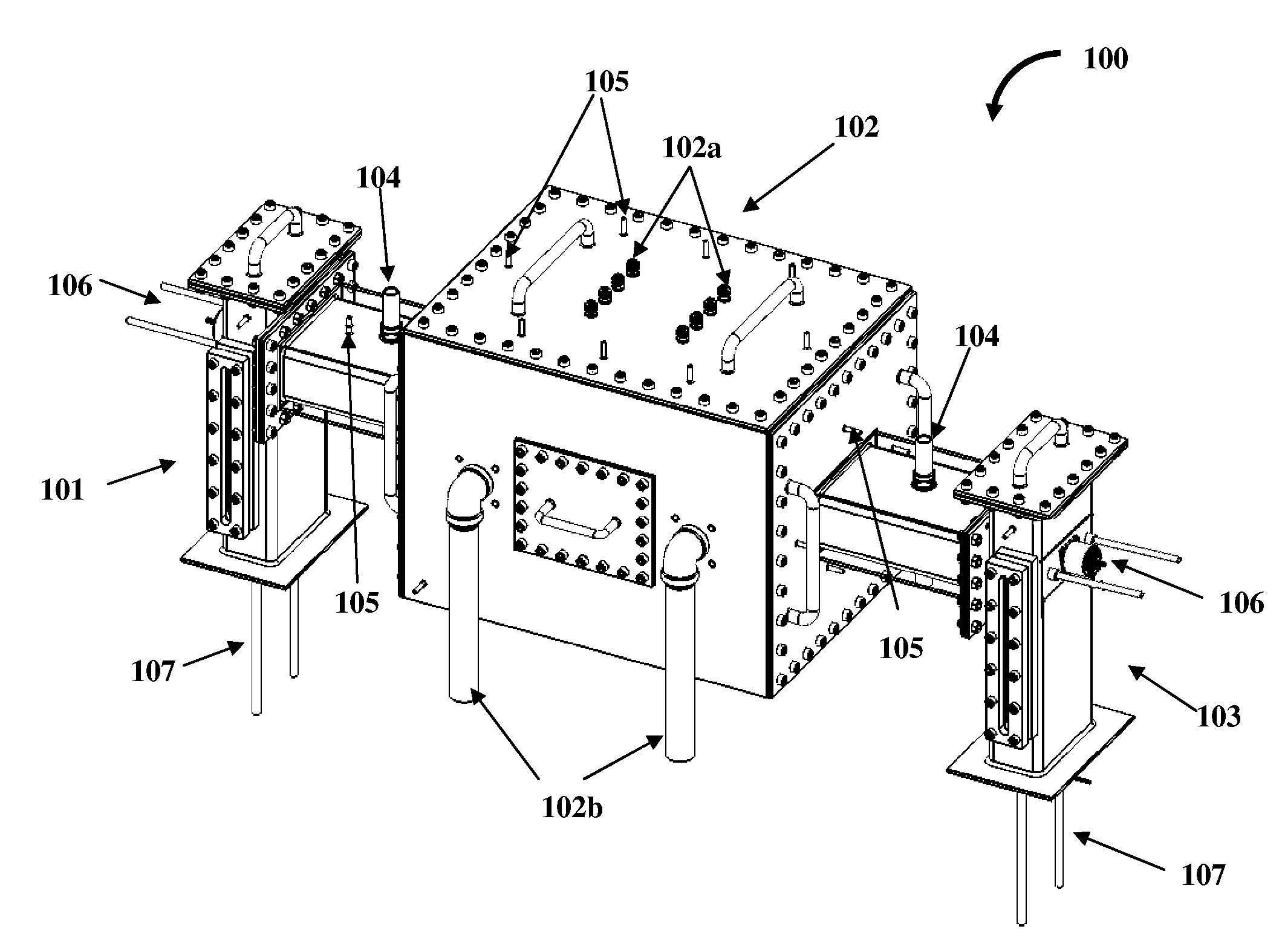
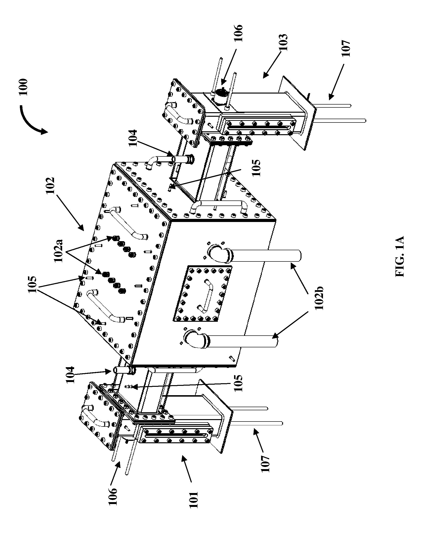
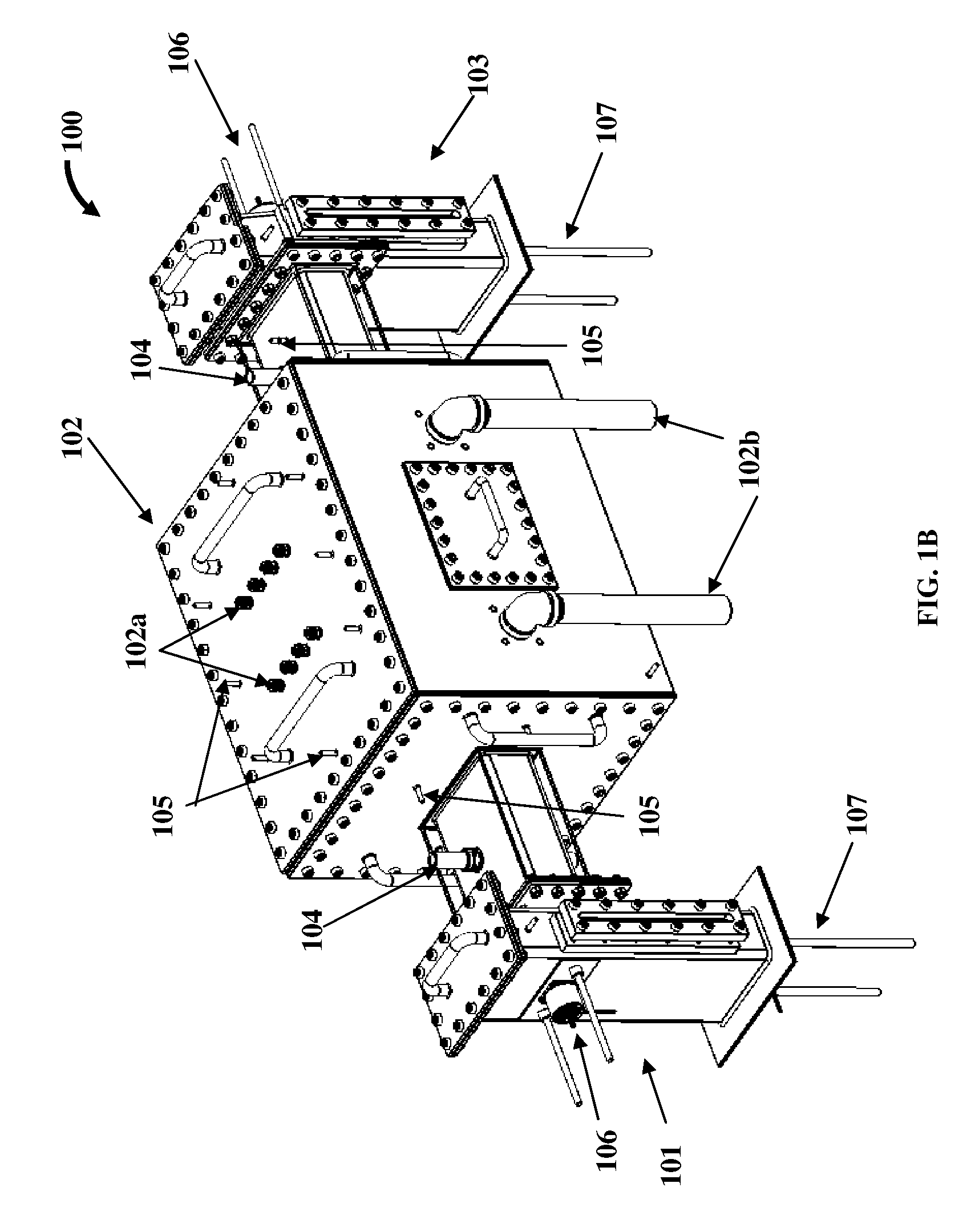
[0033]The reactor apparatus disclosed herein comprises a sample loading assembly, a metal housing, a reactor made, for example, from graphite positioned within the metal housing, and a material receiving assembly. The sample loading assembly loads samples of carbides, for example, silicon carbide (SiC), silicon carbonitride (SiCN), titanium carbide (TiC), zirconium carbide (ZrC), boron carbide (B4C), tantalum-carbide (TaC), ternary carbides such as titanium aluminum carbide (Ti2AlC), titanium silicon carbide (Ti3SiC2), molybdenum carbide (Mo2C), and any combination thereof, into the reactor. The metal carbide samples may incorporate a single metal, or may comprise two or more metals. The reactor is in closed circuit communication with the sample loading mechanism which stores and introduces the precursor metal carbides into the reactor. The metal housing maintains an inert atmosphere such as argon (Ar) around the reactor to prevent oxidation of the graphite enclosure of the reactor and graphite heating elements.

Problems solved by technology

One challenge in the synthesis of carbide derived carbons is the corrosive nature of halogen(s) at elevated temperatures with respect to the material of the processing equipment.
However, these systems limit the amount of material which can be processed, thus limiting the output of the carbide derived carbon material, typically in the order of a few grams per day.
Quartz and alumina tubes are difficult to fabricate in larger dimensions.
Also, fabrication of complex shapes with quartz and alumina is difficult or impractical.
Moreover, quartz tubes cannot be used above 1200° C. Furthermore, the halide ion etches the grain boundary, causing the quartz tube to crack.
The flow of halogens in batch reactors is generally one dimensional, that is, the gas flows from one end to the other end of the reactor, and thus results in non-uniform properties of the material.
Increased tube furnace sizes are associated with poor reaction uniformity.
Larger diameter quartz furnace tubes are associated with non-uniform reactor temperature, leading to random pore size production.
This diffusion resistance is a disadvantage of the rotary reactor, where the process involves chemical reaction between gas and solids, such as carbide derived carbon, which involves chlorine treatment of metal carbides.
The conversion of metal carbide to carbon involves a huge reduction in material density and thus would be extremely challenging to control the flow of gases, particularly when a single reactor is used for making carbide derived carbons from various carbides, which have different starting and final densities.
Removal of metal halides is also a challenge as they can contaminate the porous carbon material.

Method used


Image

  • Continuous manufacture of carbide derived carbons
  • Continuous manufacture of carbide derived carbons
  • Continuous manufacture of carbide derived carbons

Examples


example 1

[0065]This example relates to a single-step process. In this case, the feed is processed in one direction only under a single set of conditions. In an embodiment, empty trays and sample trays 205 filled and accurately weighed with a carbide material are loaded into the sample tray zone A. The empty trays, located both before and after the filled sample trays 205, are required to completely move or push the sample trays 205 with the material through the reactor 201 to the opposite sample tray zone A. The sample trays 205 are positioned such that the first sample tray 205 with the material is located in the pre-heating / de-gassing zone C. Prior to and during heating of the reactor 201, an inert gas such as argon is passed through the reactor 201. At all times, the reactor apparatus 100 is purged with an inert gas, for example, argon. The reactor 201 is heated to a predetermined temperature and is allowed to stabilize. A process or reactant gas is then introduced into the reaction / proce...

example 2

[0066]This example relates to a multi-step process. In this case, materials undergo processing in one direction at certain conditions, followed by processing in the opposite direction under different conditions, without removing the materials. In the multi-step process, there is no limit to the number of process steps. In an embodiment, empty trays and sample trays 205 filled and accurately weighed with a carbide material are loaded into the sample tray zone A. The empty trays, located both before and after the filled sample trays 205, are required to completely move or push the sample trays 205 with the material through the reactor 201 to the opposite sample tray zone A. The sample trays 205 are positioned such that the first sample tray 205 with the material is located in the pre-heating / de-gassing zone C. Prior to and during heating of the reactor 201, an inert gas such as argon is passed through the reactor 201. At all times, the reactor apparatus 100 is purged with an inert gas...


PUM

PropertyMeasurementUnit
depth of fieldaaaaaaaaaa
temperaturesaaaaaaaaaa
surface characteristicsaaaaaaaaaa

Abstract

A reactor apparatus for continuous manufacturing of porous carbon material by halogenation of carbides is provided. The reactor apparatus comprises a sample loading assembly, a reactor positioned within a metal housing and in closed circuit communication with the sample loading assembly, and a material receiving assembly. The sample loading assembly loads samples of carbides into the reactor. The metal housing maintains an inert atmosphere around the reactor. The reactor defines one or more process paths for transporting samples of carbides through a halogen atmosphere and / or a post-treatment atmosphere for yielding porous carbon material. Process vents, positioned on the reactor and the metal housing, pass inert gases and reactant gases past the samples of carbides at predetermined temperatures and exit process gases through a condenser unit. The condenser unit traps metal halide by-products. The material receiving assembly, in closed circuit communication with the reactor, removes and stores the porous carbon material.

Description

REFERENCES CITED[0001]Y. Gogotsi et al., Nature Materials, 2003[0002]R. Dash, Ph.D. thesis, Drexel University, 2006[0003]R. Dash et al., Carbon, 2006[0004]R. K. Dash et al., Microporous and Mesoporous Materials, 2004[0005]R. K. Dash et al., Microporous and Mesoporous Materials, 2005[0006]J. Chmiola et al., Science, 2010[0007]J. Chmiola et al., Science, 2006[0008]Y. Gogotsi et al., J. Am. Chem. Soc., 2005[0009]Y. Yushin et al., Biomaterials, 2006[0010]C. Portet et al, Phys. Chem. Chem. Phys., 2009PATENTS OR APPLICATIONS[0011]W. A. Mohun, Mineral Activated Carbon and Process for Producing Same, U.S. Pat. No. 3,066,099 (1962)[0012]Y. Maletin et. al., Supercapacitor and Method of Making Such a Supercapacitor, U.S. Pat. No. 6,697,249 (2004)[0013]R. Avarbz et. al., Process of Making a Porous Carbon Material and a Capacitor Having the Same, U.S. Pat. No. 5,876,787 (1999)[0014]J. Leis, M. Arulepp, and A. Perkson, Method to Modify Pore Characteristics of Porous Carbon and Porous Carbon Mater...

Claims


Application Information

Patent Timeline
Patent Type & Authority Applications(United States)
IPC IPC(8): C01B31/02B01J19/00
CPCC01B31/00C01B32/00
Inventor DASH, RANJAN
Owner Y CARBON
Why Eureka
Try Eureka