Integrated gas turbine, sagd boiler and carbon capture

a gas turbine and integrated technology, applied in the direction of emission prevention, separation process, lighting and heating apparatus, etc., can solve the problems of increasing the specific co2 emission rate, increasing the co2 emission rate, and presenting operational and logistical challenges

Inactive Publication Date: 2012-09-06
CONOCOPHILLIPS CO
View PDF4 Cites 11 Cited by
  • Summary
  • Abstract
  • Description
  • Claims
  • Application Information

AI Technical Summary

Benefits of technology

[0021]In some embodiments, the exhaust gas from the gas turbine has a temperature higher than 400° C. The sensible energy contained in the exhaust gas reduces the fuel required to generate a given quantity of steam in the boiler. However, the temperature of the exhaust gas can be adjusted before entering into the SAGD boiler, especially in the case where the high temperature may not be suitable for the ducting between the gas turbine and the SAGD boiler.

Problems solved by technology

Many of these carbon capture technologies require significant levels of electricity, the generation of which results in additional CO2 emissions, which increases the specific CO2 emissions rate.
However, this presents operational and logistical challenges.
This process has two drawbacks: (1) the steam generation efficiency of the HRSG is low due to the high excess air levels (typically 100%), and (2) CO2 capture from the cogeneration plant is not practical due to the low CO2 and high O2 levels in the HRSG flue gas.
The integrated GT-Boiler approach has not yet been used in SAGD boilers, largely because SAGD boiler burners have not been developed for TEG operation.
It is generally more difficult to capture the carbon dioxide in the exhaust gas from a gas turbine, because of the relatively low CO2 content and high oxygen content in the exhaust gas.
However, by requiring an oxidant source having oxygen content higher than 21% by volume, additional cost must be incurred to provide that oxidant source because pure oxygen is required from an air separation unit.
The drawback of the '128 process is the significant capital and operating cost associated with the air separation unit that produces the oxygen.
Furthermore, this method does not provide any carbon capture system to improve the CO2 avoidance, and therefore that system actually produces more CO2, and thus is less desirable.

Method used


Image

  • Integrated gas turbine, sagd boiler and carbon capture
  • Integrated gas turbine, sagd boiler and carbon capture

Examples


example 1

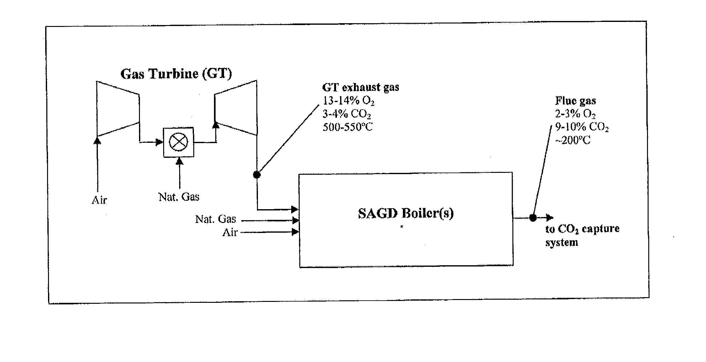
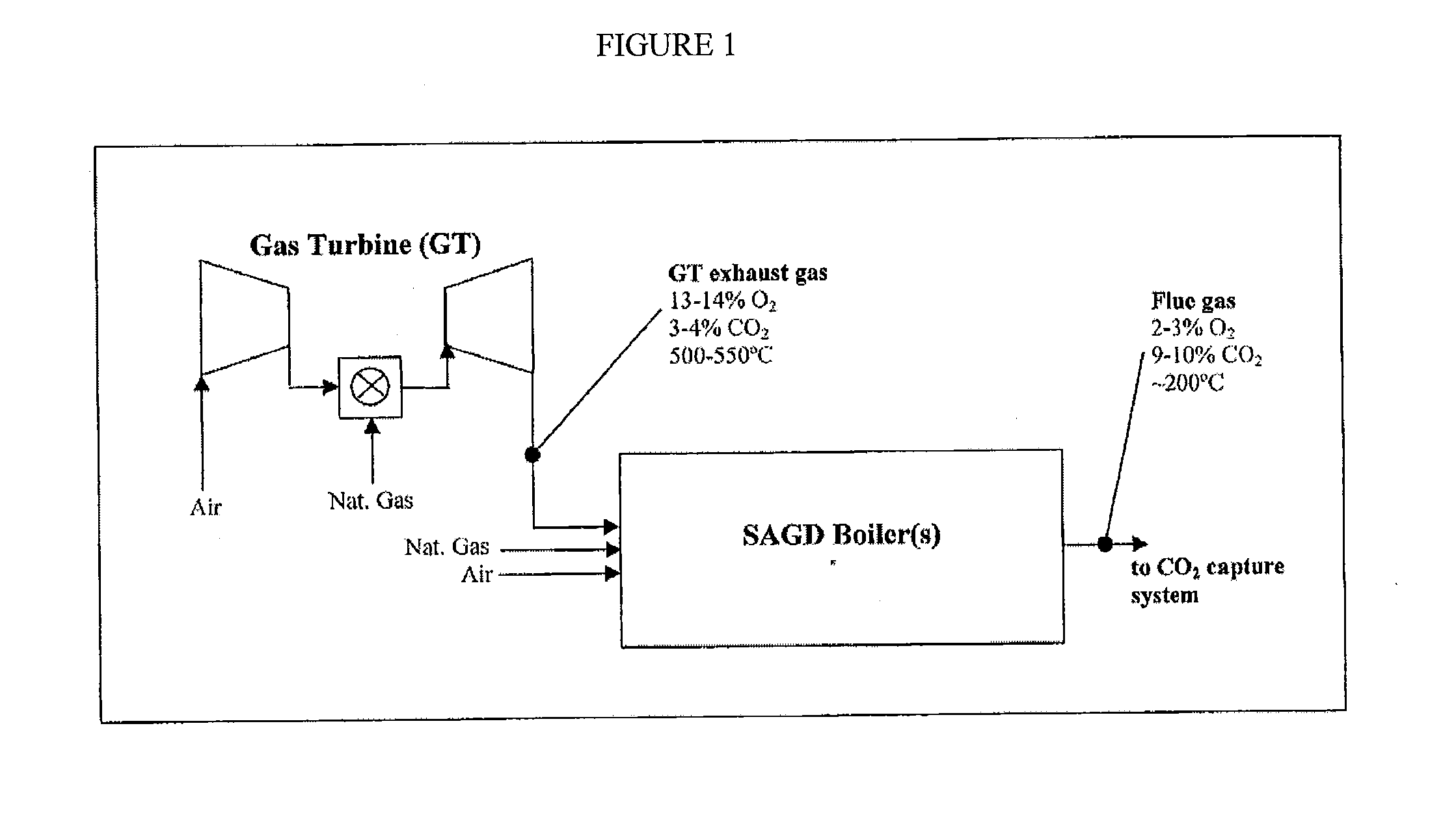
Integrated Gas Turbine-SAGD Boilers with and without Carbon Capture Systems

[0032]In this example, the invention is a process in which the flue gas from the integrated Gas Turbine-SAGD boiler system is delivered to a solvent-based carbon capture system that involves absorption of CO2 from the flue gas into the solvent, followed by thermal regeneration of the solvent to release CO2, which is further compressed. The solvent is thermally regenerated with heat from low-pressure steam generated in an auxiliary gas-fired boiler. The process modeling assumes that the MEA (monoethanolamine) solvent is used, and that a 90% CO2 capture rate from flue gas is achieved. The flue gas from the SAGD boilers as well as the flue gas from the amine regenerator boilers is delivered to the capture system. This process is shown in FIG. 2.

[0033]Table 1 shows process modeling results for four cases. Case 1 represents SAGD boilers without CO2 capture, using grid power. Case 2 represents the integrated GT-SAG...


PUM

PropertyMeasurementUnit
temperatureaaaaaaaaaa
adsorptionaaaaaaaaaa
concentrationaaaaaaaaaa

Abstract

An integrated power generation system for reducing carbon dioxide emissions is provided. The integrated system comprises a gas turbine having an air inlet, a fuel inlet and an exhaust gas outlet; a steam-assisted gravity drainage (SAGD) boiler having an inlet connected to the exhaust gas outlet of the gas turbine, a fuel inlet, an optional air inlet, and a flue gas outlet; and a carbon dioxide capture system connected to the flue gas outlet of the SAGD boiler. A method for capturing the carbon dioxide exhausted from a gas turbine and a SAGD boiler is also provided.

Description

CROSS-REFERENCE TO RELATED APPLICATIONS[0001]This application is a non-provisional application which claims the benefit of and priority to U.S. Provisional Application Ser. No. 61 / 449,441 filed Mar. 4, 2011, entitled “Integrated Gas Turbine, SAGD Boiler and Carbon Capture,” which is hereby incorporated by reference in its entirety.FIELD OF THE INVENTION[0002]The invention relates to more efficient methods of generating power that are also less polluting.BACKGROUND OF THE INVENTION[0003]With the emerging awareness of global warming and greenhouse gases, carbon capturing becomes an important consideration, especially in the power generation industry. Various carbon capture processes are being investigated for fossil-fuel fired boilers that produce steam for Steam Assisted Gravity Drainage (SAGD) operations. Many of these carbon capture technologies require significant levels of electricity, the generation of which results in additional CO2 emissions, which increases the specific CO2 e...

Claims


Application Information

Patent Timeline
Patent Type & Authority Applications(United States)
IPC IPC(8): F02C3/34
CPCF02C6/18F23L2900/07002Y02E20/16Y02E50/12F01K23/10F01K13/00F22B1/1815F22B1/1861F23J2215/50Y02C10/06Y02C10/08Y02C10/10Y02E20/322B01D53/002B01D53/04B01D53/1475B01D53/229B01D2252/20405B01D2252/20421B01D2252/20484B01D2257/504B01D2258/0283F23J2219/40F23J2900/15061F23L2900/07001Y02E20/14Y02A50/20Y02C20/40Y02E20/32Y02E50/10
Inventor MACADAM, SCOTT
Owner CONOCOPHILLIPS CO
Why Eureka
Try Eureka