System for Fabricating a Pattern on Magnetic Recording Media

a technology of magnetic recording media and pattern, which is applied in the field of magnetic recording media fabrication, can solve the problems of high cost per bit, high cost of solid-state memory, and physical limitations of memory density, and achieve the effects of extending the use between external services, reducing the system footprint, and improving processing efficiency

Inactive Publication Date: 2012-09-06
VEECO INSTR
View PDF0 Cites 199 Cited by
  • Summary
  • Abstract
  • Description
  • Claims
  • Application Information

AI Technical Summary

Benefits of technology

[0109]The nature of the pattern transfer process is that a near net zero (total deposition approximately equal to total removal), or a net removal will likely be normal. Nonetheless, small areas of the MDC's substrate holding flexures and fixtures may accumulate process residues or be eroded because of shadowing, and will eventually need to be serviced or replaced. In either case, the flexures and fixtures are screw-in or snap-in parts that may be part of a robotically changeable cartridge. Cartridges comprising a set of mounted flexures and other substrate holding fixtures may be replaced periodically by a robot in the system, thus extending use between external services.
[0110]One embodiment of the present invention also uses optional vertical extensions to the p...

Problems solved by technology

This “continuous media” technology has physical limitations for memory density, since, as the domains become smaller, their influence on each other increases, and an unacceptable level of spontaneous switching occurs under even small thermal influences, a physical effect called “super-paramagnetism.”
Solid-state memory, while very dense, is still roughly two orders of magnitude more expensive, per bit, than magnetic memory.
Ultimately, there is a limit to the maximum coercivity of the media that can be successfully written with conventional heads, so alternatives must be pursued.
In addition to the super-paramagnetic issue, increases in areal density lead to cross track interference that degrades the signal-to-nois...

Method used


Image

  • System for Fabricating a Pattern on Magnetic Recording Media
  • System for Fabricating a Pattern on Magnetic Recording Media
  • System for Fabricating a Pattern on Magnetic Recording Media

Examples


first embodiment

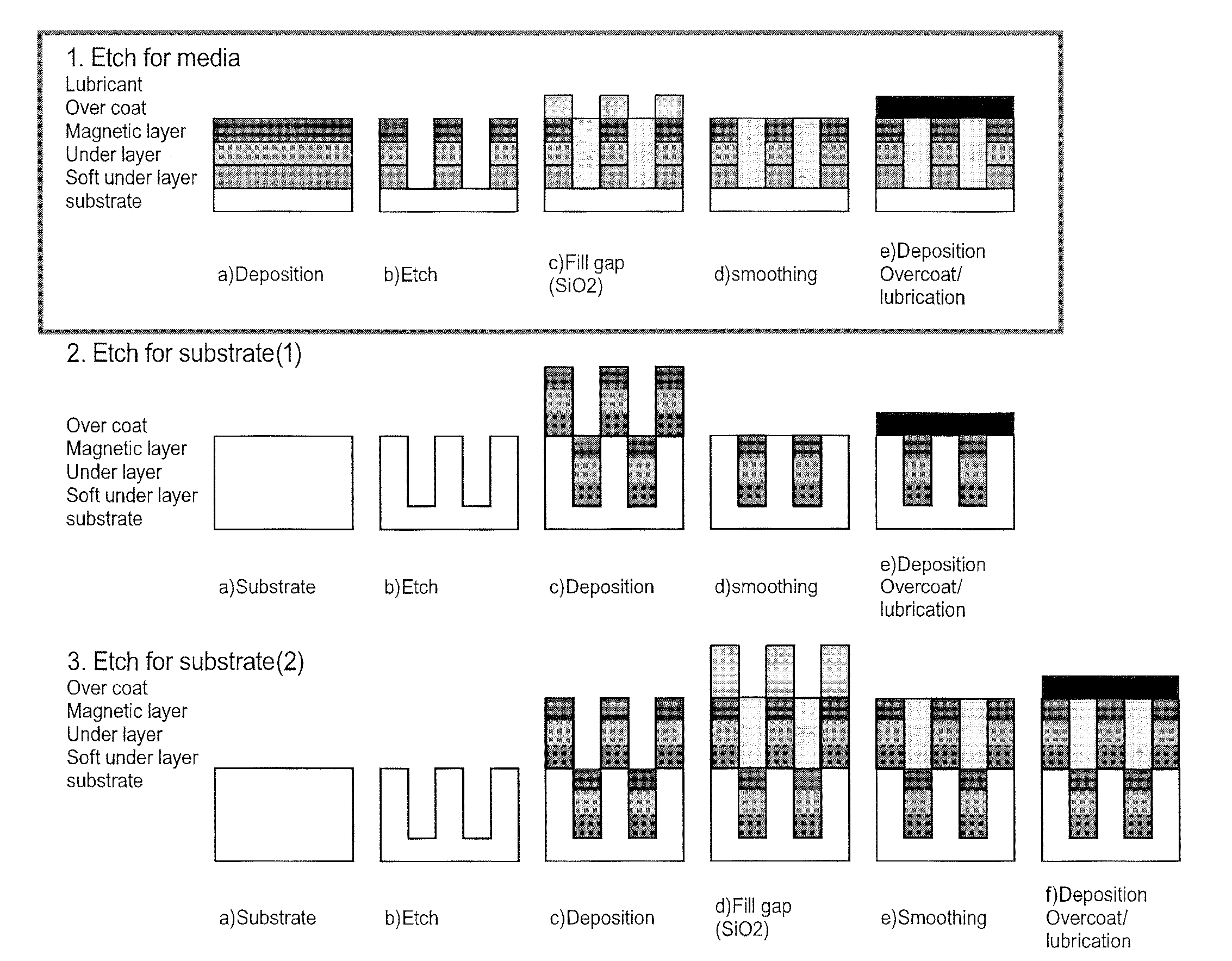
[0143]In one embodiment of the present invention, substrates such as magnetic memory storage discs, are processed in a vertical orientation on both sides simultaneously, through the process steps of pattern transfer, gap fill, planarization, and overcoat deposition, at a high rate through a linear system that requires relatively small floor space. This processing sequence is represented graphically in the outlined approach labeled “1. Etch for Media” of FIG. 11. FIG. 11 also has two other approaches. For all three, the labels along the left of the figure correspond to the graphically drawn layers.

[0144]An embodiment of a linear processing system consistent with the “Etch for Media” process sequence , is represented in FIG. 12.

[0145]This embodiment has a linear configuration of eight process stations configured as Etch, Cool, Etch, Ash (as shown, it is within the second etch), Gap Fill, Planarization A, Planarization B, and Overcoat. Under each process station is one segment of a Tra...

first additional embodiment

[0169]In another embodiment, the process sequence described above is applicable to the approach represented graphically in the outlined approach labeled “1. Etch for Media” in FIG. 11. However, there are several alternative processing sequences in which the steps of etching, deposition and planarization are in a slightly different order, for example those if the lower areas of FIG. 11. Except for the number and sequence of processes, the operation of these embodiments proceeds in essentially the same way as the operation of the preferred embodiment, described above.

second additional embodiment

[0170]In another embodiment a hard mask may be used to pattern the storage layer since the imprint mask may not have sufficient etch resistance to survive during the storage layer etch. A hard mask strategy involving bi-layer hard masks is illustrated in FIGS. 15A-15I. The captions in those figures mention certain chemical elements and compounds that are used, but those, and any mentioned in this description are examples, and are not limiting. The disk is loaded with a lower hard mask and upper hard mask already under the imprinted photoresist. The top hard mask layer should be chosen such that it can be etched readily without eroding too much of the resist while remaining relatively intact during the etch of the bottom hard mask layer, while the bottom hard mask layer should have sufficient etch resistance to survive the storage layer etch. Among choices for the upper hard mask are Cr, NiFe that may be etched using Ar, or Ti or Ta that may be etched by using Ar / CF4 / O2 , or Al2O3 or...


PUM

PropertyMeasurementUnit
Angleaaaaaaaaaa
Processing propertiesaaaaaaaaaa
Orderaaaaaaaaaa

Abstract

An inline processing system for patterning magnetic recording layers on hard discs for use in a hard disc drive. Discs are processed on both sides simultaneously in a vertical orientation, in round plate-like holders called MDCs. A plurality (as many as 10) discs are held in a dial carrier of the MDC, and transferred from one process station to another. The dial carrier of the MDC may be rotated and/or angled at up to 70° from normal in each process station, so that one or a plurality of process sources may treat the discs simultaneously. This configuration provides time savings and a reduction in the number and size of process sources needed. A mask enhancement process for patterning of magnetic media, and a filling and planarizing process used therewith, are also disclosed.

Description

FIELD OF THE INVENTION[0001]This invention relates to the fabrication of magnetic recording media, in particular rigid and hard disk media onto which magnetic recording material is deposited and patterned into discrete magnetic domains. More particularly, this invention relates to the integration of several processing steps within a single integrated processing tool for the production of patterned media.BACKGROUND OF THE INVENTION[0002]Conventional hard disc memory storage uses a continuous magnetic film (aka continuous media), recording information onto the film by orienting the magnetization of small clusters of its metal grains into individual domains, or bits. This “continuous media” technology has physical limitations for memory density, since, as the domains become smaller, their influence on each other increases, and an unacceptable level of spontaneous switching occurs under even small thermal influences, a physical effect called “super-paramagnetism.”[0003]Modern electronic...

Claims


Application Information

Patent Timeline
IPC IPC(8): G11B5/84B44C1/22B05C13/02
CPCC23C14/042C23C14/046C23C14/505G11B5/855H01L21/67754H01L21/67709H01L21/67712H01L21/67718H01L21/67742H01L21/67173G11B5/65
Inventor PARANJPE, AJITLUSE, TODD A.FREMGEN, ROGER P.SRINIVASAN, NARASIMHANDRUZ, BORIS L.ROOK, KATRINACELARU, ADRIAN
Owner VEECO INSTR
Why Eureka
Try Eureka